Ball-point pen

a ball-point pen and pen body technology, applied in the field of ball-point pen, can solve the problems of inability to solve problems, inability to write, and inability to starve and draw ink, so as to prevent scratchiness against paper surface, stable ink flow amount, and reliable sealing performance

Inactive Publication Date: 2000-07-04
MITSUBISHI PENCIL CO LTD
View PDF16 Cites 30 Cited by
  • Summary
  • Abstract
  • Description
  • Claims
  • Application Information

AI Technical Summary

Benefits of technology

Therefore, the open V-shaped tapered portion located in the rear of the press formed portion, provides the function of preventing scratchiness against the paper surface as well as providing the function of forming a wall of regulated thickness during press forming and hence stabilizing the ink flow amount.
Further, the provision of a spring, which has an end turn portion at its rear end as appropriate and hence provides continuous stable urging of the ball, produces a reliable sealing performance as well as secures reliable sealing when the ball-point pen is oriented upward. In particular, the present invention functions most effectively when it is applied to an intermediate type ball-point pen using an ink having a relati...

Problems solved by technology

However, in the case of a clicking type ball-point pen as well as in the case where the user has forgotten to fit the cap, in the case of a writing implement where a volatile type of ink is necessary, and in other cases, ink starvation and air drawing tend to occur, and the writing implement itself sometimes tends to become disabled.
In particular, these problems have not been resolved for so-called intermediate type ball-point pens which use ink of a medium viscosity and present intermediate properties between oily and aqueous ball-point pens.
Some ball-point pens which are improved as to these problems have been invented, but no products are yet found which are free from the problem of abrasion in the interior of the point assembly.
When manipulation with a barrel mechanism is used as a...

Method used


Image

  • Ball-point pen
  • Ball-point pen
  • Ball-point pen

Examples


first embodiment

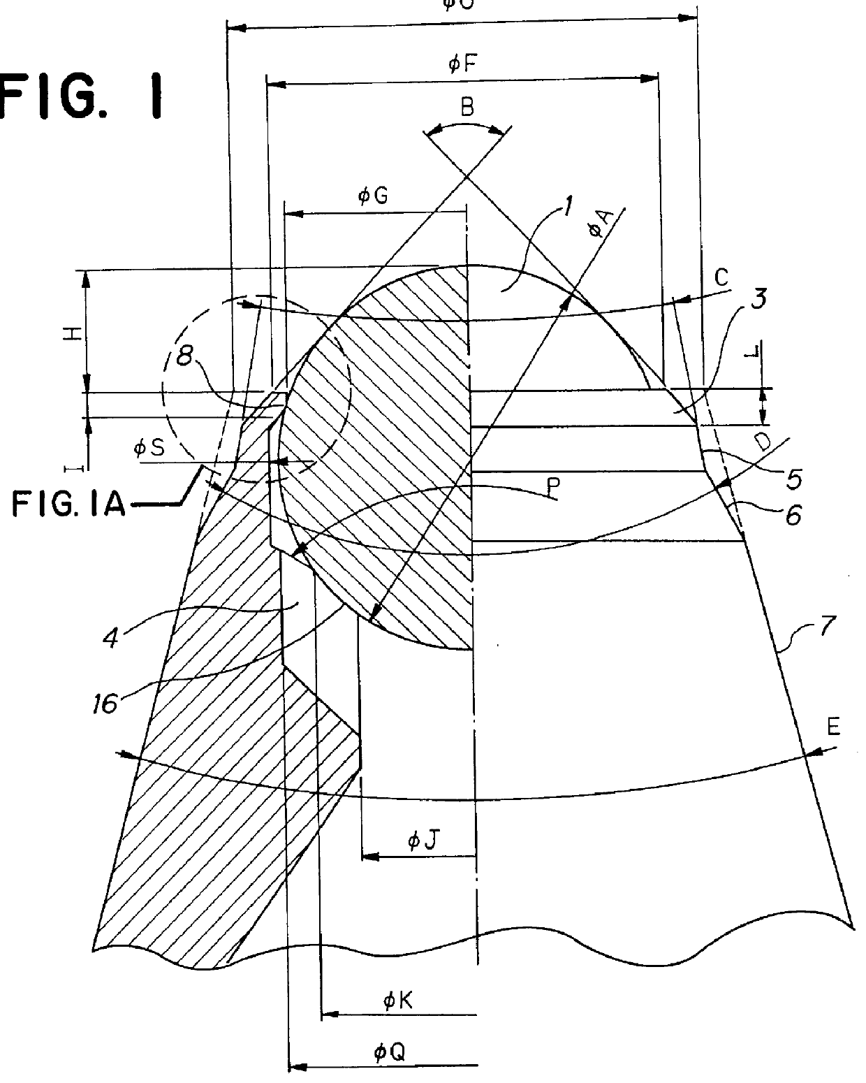
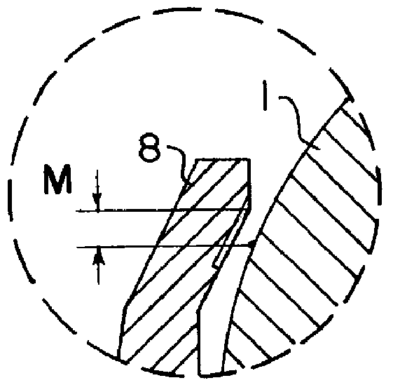
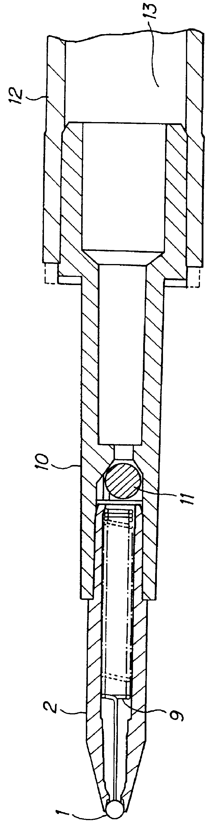
FIGS. 1 to 3 illustrate an example of a ball-point pen of the present invention, and description will be made referring to the figures.

An ink reservoir tube stores an ink, a greasy follower at the rear of, and in contact with, the ink and a solid follower rod 15 having a specific gravity approximately equal to that of the follower, with the ink and follower having been degassed during manufacturing. The follower 14 is effective in preventing backward leakage and inhibiting evaporation. The follower rod 15 is floating in the follower and hence produces capillary force so as to enable the follower to readily follow the ink 13 as the ink is consumed during writing. The following rod also prevents the follower from being broken and leaking when the pen is impacted by being dropped. A writing ball 1 is fitted at the tip of the point assembly 2 so as not to fall off by the combination of the front side press formed portion and the ball seat 16 on the rear side. The ball 1 is loosely held ...

example 1

I=0.2; L=0.02A; C=20.degree.; D=60.degree.; H=0.35A; F=1.08A; G=0.97A, other settings were the same as conventional example 2.

example 2

I=0.9; L=0.14A; H=0.3A; F=0.92A; G=0.91A, other settings were the same as example 1.


PUM


Abstract

PCT No. PCT/JP97/04264 Sec. 371 Date Jul. 8, 1999 Sec. 102(e) Date Jul. 8, 1999 PCT Filed Nov. 21, 1997 PCT Pub. No. WO98/30401 PCT Pub. Date Jul. 16, 1998A ball-point pen having a point assembly, in which the inside and outside diameters of a press formed portion (3) for preventing a ball (1) from slipping out, a sealing face (8), the projected amount of the ball, the diameter of a ball seat (16), the longitudinal backlash and the like are formed in optimized dimensions, sealing face (8) is configured so as to have a radius of curvature approximately equal to that of ball (1), and ball seat (16) having a radius of curvature approximately equal to that of ball (1) is formed in the rear of ball (1), while a multiple number of channels (4) for leading ink (13) to the pen point are provided inside the point assembly.

Description

The present invention relates to parts of a point assembly in which a ball disposed at its tip as a writing element is loosely held whilst being kept from slipping out with appropriately sized clearances which establish a flow passage of ink, and the invention further relates to improvement of a ball-point pen using the parts.Conventionally, there have been ball-point pens and small-tube type writing implements where a cap with a sealing element therein composed of elastic rubber, etc., to seal the pen point is used when the pen is not used for long periods of time, in order to prevent evaporation of ink and in order to prevent ink starvation which would occur due to drawing of air through the pen point when the pen is impacted by being dropped as well as so-called forward leakage, that is, ink drip from the pen point. However, in the case of a clicking type ball-point pen as well as in the case where the user has forgotten to fit the cap, in the case of a writing implement where a ...

Claims


Application Information

Patent Timeline
IPC IPC(8): B43K1/08B43K1/00
CPCB43K1/084B43K1/086B43K1/08
Inventor FURUKAWA, KAZUHIKO
Owner MITSUBISHI PENCIL CO LTD
Why Eureka
Try Eureka