Method of making a gangway bellows for rolling stock

a technology of gangway and bellows, which is applied in the direction of gangway, railway body, coupled vehicle gangway, etc., can solve the problems of large number of corrugations of the bellows, and achieve the effect of stiffening or strengthening the stiffness of certain corrugations

Inactive Publication Date: 2000-07-11
LE JOINTS FRANCAIS SA
View PDF2 Cites 12 Cited by
  • Summary
  • Abstract
  • Description
  • Claims
  • Application Information

AI Technical Summary

Benefits of technology

Another aim of the invention is to provide a bellows in which the base material makes it possible to adapt to demand and to fire/smoke classifications.
Yet another aim of the invention is to make it poss...

Problems solved by technology

In use, such devices are not immune from leaks due to the stitching, while their capacity for deformation remains limited because of the orientation of the textile medium, thus having the effect of leading to bellows having a large number of corrugations.
There therefo...

Method used


Image

  • Method of making a gangway bellows for rolling stock
  • Method of making a gangway bellows for rolling stock
  • Method of making a gangway bellows for rolling stock

Examples


Embodiment Construction

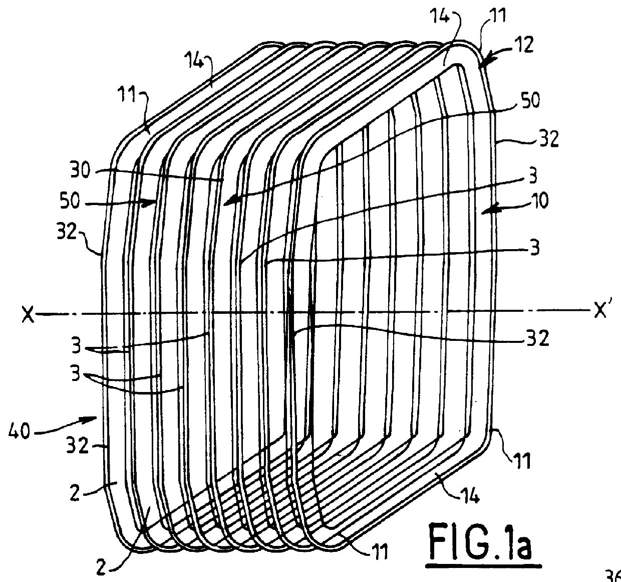
The gangway bellows shown in FIG. 1 is a bellows 40 for providing a corridor connection between two cars and it comprises a plurality of corrugated regions or corrugations 2 which are vulcanized into shape without stitching and without adhesive.

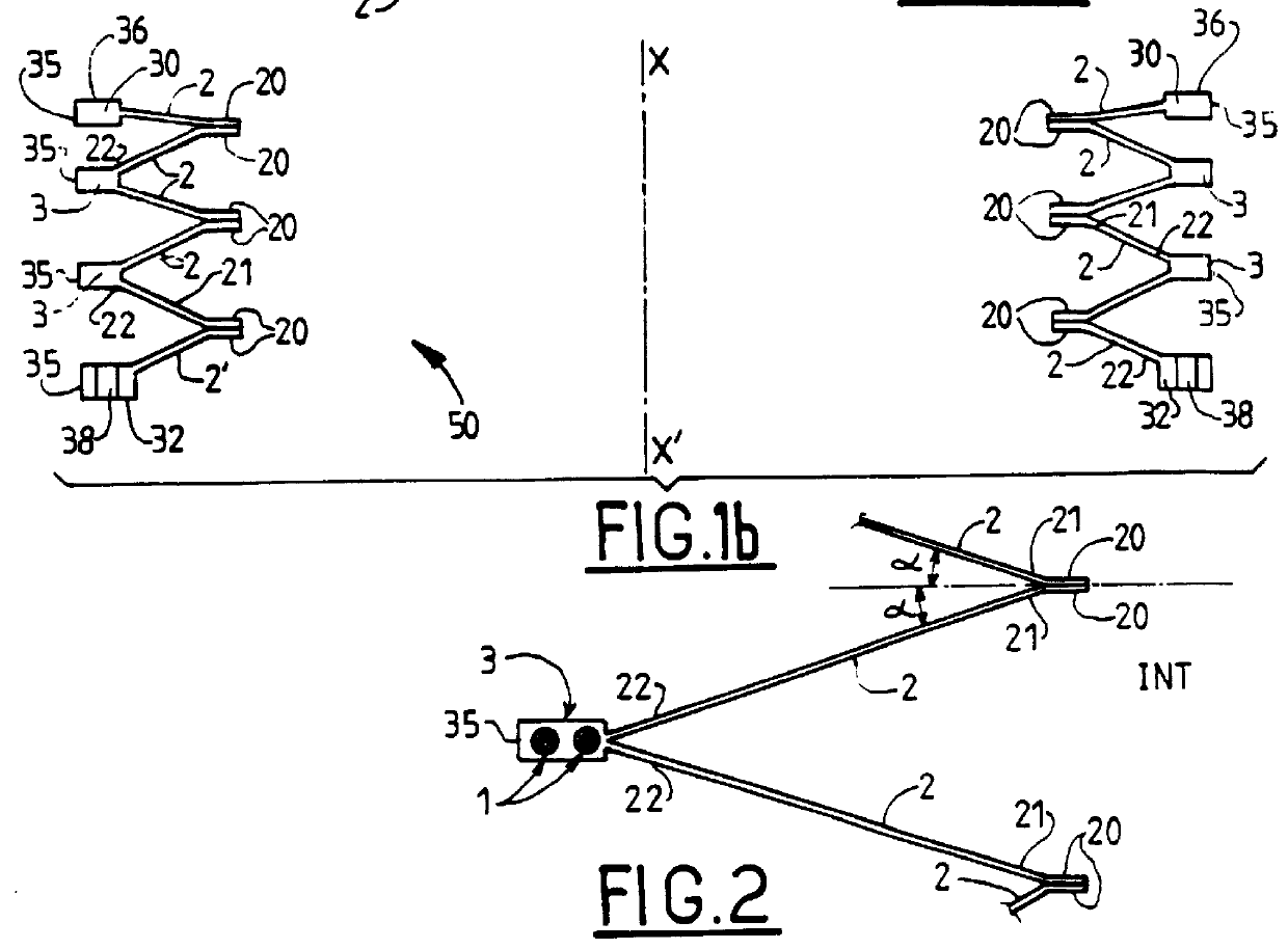
As shown in FIG. 1a and 2, each corrugation is in the form of an inclined frame 2 which is substantially plane in section, being inclined at an angle a relative to the normal to the longitudinal axis XX' of the bellows. The inside edge 21 of the frame 2 is extended by a plane region 20 of closed outline which is vulcanized to the plane region 20 of the corrugation 2 adjacent thereto. By way of example, the module shown in FIG. 1b has six corrugated regions 2.

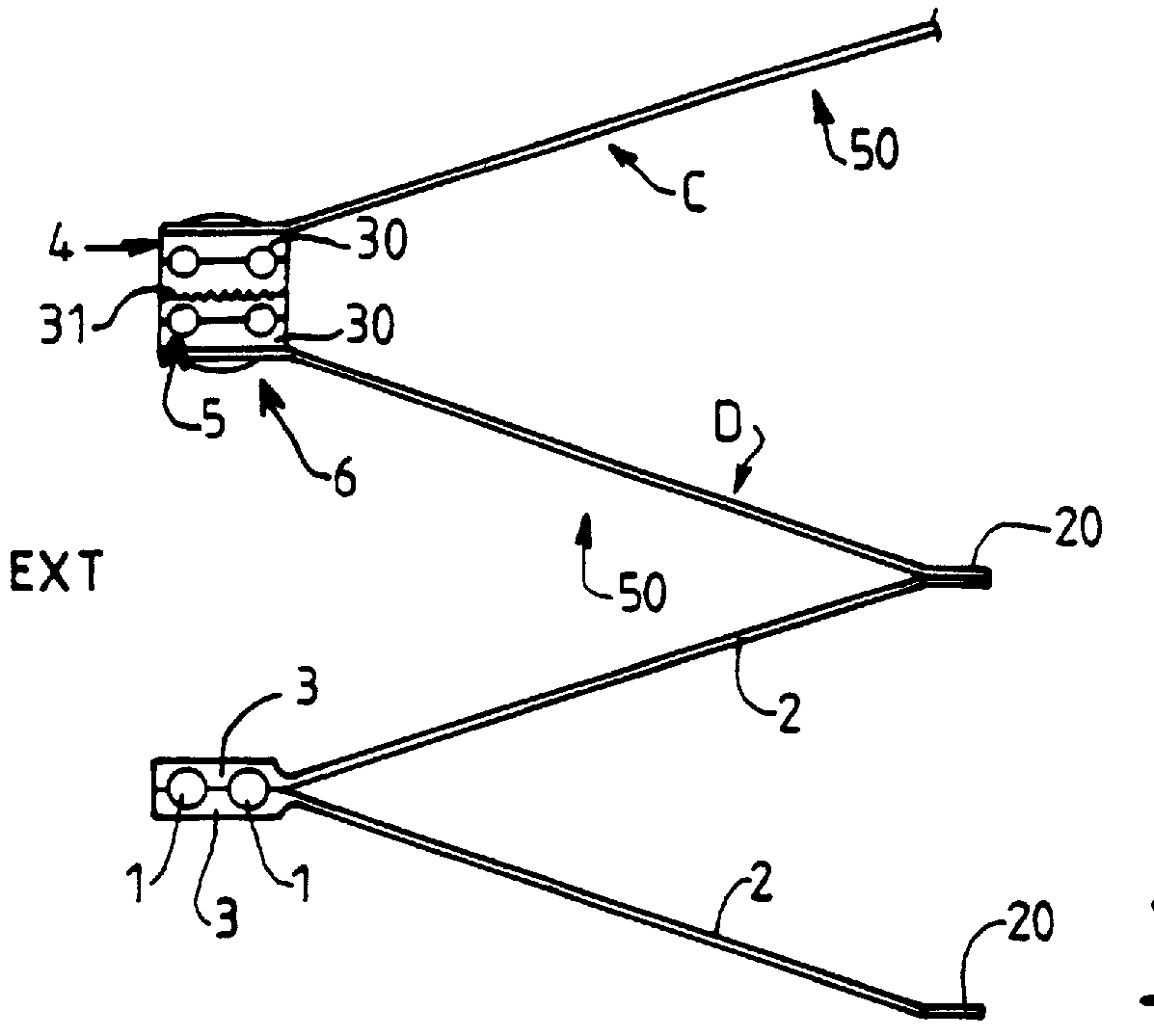
The outside edge 22 of the frame 2 is extended by an external stiffener 3 which is common to two adjacent frames 2. The stiffener 3 has a cross-sectional area that is considerably greater than that of the frame regions 2, so it is the frames 2 constituting the flexible corrugations that e...


PUM


Abstract

A gangway bellows for rolling stock, where the bellows has corrugated regions forming a deformable volume, and comprises a plurality of assembled-together modules, each module being made of a rubber-base material and including at least two corrugated regions that are assembled together by vulcanization.

Description

The present invention relates to a gangway bellows for rolling stock, e.g. for the purpose of providing a link between two cars of a moving assembly such as a train, a tram, a bus, or any other rail or road vehicle.It is known that rail cars include at an end of the body proper a concertina-like bellows for interconnecting the cars and for providing protection against the weather for passengers moving between the cars.Certain known devices make use of a riveted configuration made of leather with reinforcement made of aluminum extrusions, while other devices are built up from cloth coated on both faces with polyvinyl chloride (PVC), or with rubber, which is then cut and assembled by adhesive or stitching, and is finally reinforced around the external outline of the corrugations by aluminum extrusions that are bent to shape and crimped on.In use, such devices are not immune from leaks due to the stitching, while their capacity for deformation remains limited because of the orientation...

Claims


Application Information

Patent Timeline
IPC IPC(8): B61D17/04B61D17/22
CPCB61D17/22Y10T29/49877
Inventor PETIT, JEAN-CLAUDE
Owner LE JOINTS FRANCAIS SA
Why Eureka
Try Eureka