Magnet valve with pressure limitation for slip-controlled motor vehicle brake systems

a technology of brake system and magnet valve, which is applied in the direction of braking system, valve operating device/release device, braking components, etc., can solve the problems of irritating noise in the motor vehicle interior, especially irritating

Inactive Publication Date: 2000-07-11
ROBERT BOSCH GMBH
View PDF22 Cites 21 Cited by
  • Summary
  • Abstract
  • Description
  • Claims
  • Application Information

AI Technical Summary

Problems solved by technology

Because the pump operation is pulsating, pressure surges arise in the downstream portion of the brake line and can cause irritating noise in the motor ve...

Method used


Image

  • Magnet valve with pressure limitation for slip-controlled motor vehicle brake systems
  • Magnet valve with pressure limitation for slip-controlled motor vehicle brake systems
  • Magnet valve with pressure limitation for slip-controlled motor vehicle brake systems

Examples


Embodiment Construction

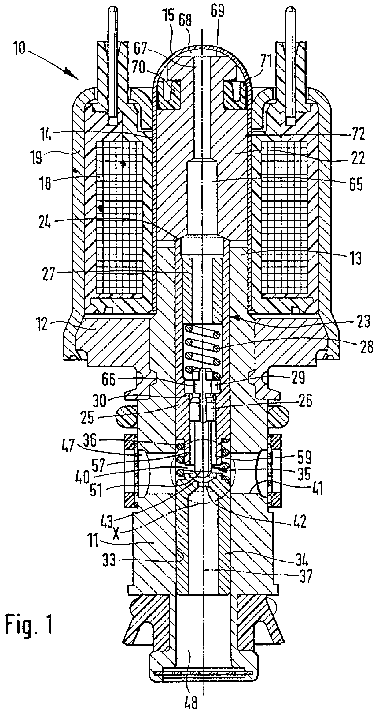
The magnet valve 10 shown in FIG. 1, with pressure limitation, is intended for use in slip-controlled brake systems of motor vehicles. The magnet valve 10 has a valve housing 11, which is meant to be received in a valve block, not shown, and is solidly joined to a yoke disk 12. The valve housing 11 is continued outward, past the yoke disk 12, in the form of a pole core 13. A closed, tubular valve dome 14 is mounted on the pole core 13. It is tightly joined to the pole core 13 by welding. Remote from the pole core, the valve dome 14 is terminated with a hemispherical cap 15.

The valve dome 14 is engaged circumferentially by an annular magnet coil 18. A bell-shaped housing 19 engages the valve dome 14 on one side; on the other, this housing is joined to the yoke disk 12.

In the valve dome 14 closed on the coil side, a substantially circular-cylindrical magnet armature 22 is received so as to be longitudinally movable. A valve tappet 23 is braced against the magnet armature 22. The magne...


PUM


Abstract

PCT No. PCT/DE95/01386 Sec. 371 Date Apr. 28, 1997 Sec. 102(e) Date Apr. 28, 1997 PCT Filed Oct. 10, 1995 PCT Pub. No. WO96/13414 PCT Pub. Date May 9, 1996A magnet valve with low noise upon shutoff from the pressure limiting function. The magnet valve has a two-part valve tappet, whose inner valve tappet part has the closing member of a seat valve. The closing member is circumferentially engaged in spaced-apart fashion, forming a gap space, by a tubular portion of the outer valve tappet part. From the gap space, a pressure fluid conduit leads to a control chamber, which is located between the face end, remote from the seat valve, of a magnet armature that cooperates with the valve tappet, and a valve dome. Upon shutoff of the magnet valve, the seat valve changes from its closing position to a partly open position, in which dynamic pressure in the gap space becomes operative and is transmitted through the pressure fluid conduit into the control chamber. The hydraulic force that is operative there on the magnet armature acts counter to the opening forces of the magnet valve and slows down its opening motion. Because of the thus-throttled flow of pressure fluid through the seat valve, a pressure surge is averted. The magnet valve can be used in slip-controlled motor vehicle brake systems.

Description

PRIOR ARTThe invention is based on a magnet valve for slip-controlled motor vehicle brake systems.One such magnet valve is already known (German Patent Disclosure DE 42 34 749 A1) U.S. Pat. No. 5,496,100, which in slip-controlled brake systems of motor vehicles is disposed in a brake line between the master cylinder and the compression side of a high-pressure pump that pumps into the brake line, as described in the German Patent Reference DE 40 41 506 A1 U.S. Pat. No. 5,167,442. In ASR traction control, the magnet valve is switched into its closing position and the pressure limiting function is activated. Once the pump pressure exceeds the opening pressure of the valve, the seat valve moves counter to the force of the pressure limiting spring into the partly open position, so that pressure fluid can flow out to the master cylinder. Because the pump operation is pulsating, pressure surges arise in the downstream portion of the brake line and can cause irritating noise in the motor ve...

Claims


Application Information

Patent Timeline
IPC IPC(8): B60T8/36B60T8/50B60T8/34F16K31/06F16K47/02
CPCB60T8/365B60T8/5025Y10S303/90Y10S303/901B60T8/36
Inventor OEHLER, MARTINHOHL, GUENTHERHUEBNER, HANS-PETERMITTWOLLEN, NORBERT
Owner ROBERT BOSCH GMBH
Why Eureka
Try Eureka