Spring diaphragm for shut-off valves and regulators

a technology of valve valve and spring, which is applied in the direction of valve operating means/release devices, diaphragm valves, engine diaphragms, etc., can solve the problems of increasing the amount of work going into its manufacture, reducing the lifetime of the valve and its reliability during service, and reducing the weight of the valve. , to achieve the effect of increasing the lifetim

Inactive Publication Date: 2000-08-01
RAPHAEL VALVES INDS 1975
View PDF11 Cites 79 Cited by
  • Summary
  • Abstract
  • Description
  • Claims
  • Application Information

AI Technical Summary

Benefits of technology

In order to increase the lifetime, springy ribs which create the force and the unit pressure needed to ensure hermetic sealing between the diaphragm and the valve body are provided on the curvilinear concave surface of the lower part of the flexible e

Problems solved by technology

One deficiency of such diaphragm is the fact that it can be operated (the valve can be opened and closed) only by manual control and can be employed only in shut-off valves.
Such a diaphragm design cannot be employed in regulator valves, i.e., in devices which automatically regulate the value of the pressure or pressure drop.
Another shortcoming of the design of this diaphragm is the fact that its operation requires a manual drive mechanism that includes several parts (an actuator, a screw, a bushing, and a handwheel), which increases the weight of the valve and the amount of work going into its manufacture and reduces the lifetime of the valve and its reliability during service.
One deficiency of this diaphragm is the fact that at low pressure drops and low flow r

Method used


Image

  • Spring diaphragm for shut-off valves and regulators
  • Spring diaphragm for shut-off valves and regulators
  • Spring diaphragm for shut-off valves and regulators

Examples


Embodiment Construction

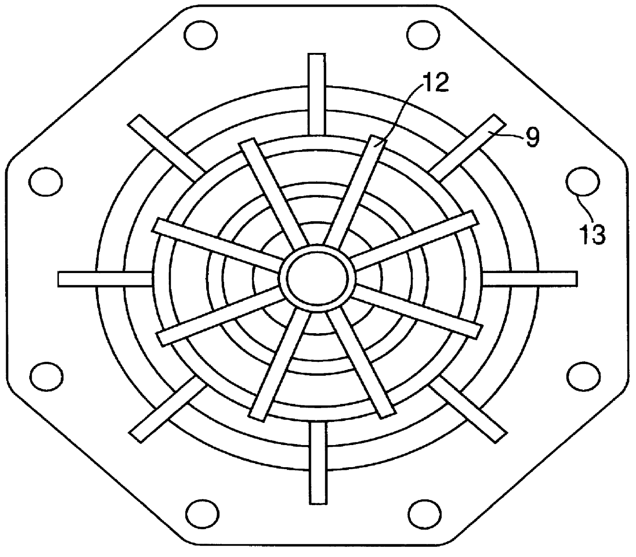
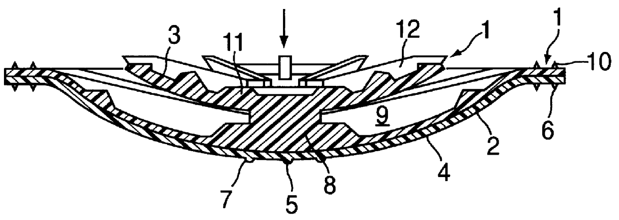
The diaphragm seen in FIG. 1 consists of flexible elastic disk 1, which is constructed in the form of two parts joined to one another, i.e., lower part 2 and upper part 3.

Within the lower part there is a scarcely deformable, thin stiff elastic sheet 4, for example, of cotton or nylon, which imparts the necessary stiffness to the diaphragm operating under pressure.

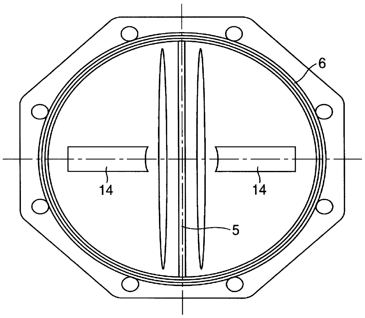
On the convex surface of the lower part 2 there is provided a central hermetically sealing ridge 5, which is joined to annular hermetically sealing ridges 6, with the aid of which hermetic sealing is ensured between the diaphragm and the valve body.

On both sides of the hermetically sealing ridge 5 there are provided ribs 7, which are intended for damping the noise and vibrations appearing during operation of the valve.

In the central part of the concave surface of the lower part 2 there is a solid disk 8, from which springy ribs 9 branch out in the radial direction at equal distances from one another.

The radically arranged, ...


PUM


Abstract

A spring diaphragm for use in automatic hydraulic control valves of the type having a valve body having an inlet chamber, and an outlet chamber and a spring diaphragm interposed between the inlet and outlet chambers, which spring diaphragm, as a result of hydraulic pressure, is automatically moveable between an open and closed position, in which the diaphragm allows and prevents, respectively, communication between the inlet and outlet chambers, includes a two-part diaphragm element including a first lower part and second upper part generally spaced apart from one another, the first lower part being in the form of a flexible elastic disc which performs the function of a hermetic seal between the inlet and outlet chambers when the spring diaphragm is in the closed position and the second upper part being connected to the first part and being in the form of a resilient disc which performs the function of a spring to normally bias the spring diaphragm from the open to the closed position. The first and second parts each have resilient spring-like ribs on the first lower part serving to aid hermetic sealing when the diaphragm is in the closed position and the ribs on the second upper part serve to provide a main force to bias the diaphragm into the closed position.

Description

FIELD AND BACKGROUND INVENTIONThe present invention relates to diaphragm used in shut-off valves and regulators and more particularly to an improved spring diaphragm for shut-off valves and regulators for the hermetic separation of adjacent chambers of valves under pressure, as well as for the possibility of regulating the magnitude of the flow passing through a pipeline.The spring diaphragm according to the invention is of unique construction, which will be referred to hereinafter as "two-storey diaphragm", can be employed in devices used in water-supply systems and in pipelines transporting petroleum, gas, various kinds of acids and bases, and other liquid mixtures and solutions.A diaphragm which is intended for similar purposes and can be employed in similar devices is known (see "Fluid Controlling Diaphragm Valve," England, Classes: 135, Fick 7 / 16, No. 34131).This diaphragm has the form a disk of molded shape made of rubber, at its center there is provided a bolt for joining the...

Claims


Application Information

Patent Timeline
IPC IPC(8): F16K7/12
CPCF16K7/126Y10T137/7762
Inventor FRENKEL, BORIS
Owner RAPHAEL VALVES INDS 1975
Why Eureka
Try Eureka