Wheel lift caddy

a technology for lifting caddy and wheel, which is applied in the direction of wheel mounting apparatus, manufacturing tools, transportation and packaging, etc., can solve the problems of inability to reliably reliably hold, grip and maneuver the lifting apparatus, and the overall apparatus structure is too light and frail to reliably

Inactive Publication Date: 2000-08-01
GARNETT WINFIELD J
View PDF5 Cites 34 Cited by
  • Summary
  • Abstract
  • Description
  • Claims
  • Application Information

AI Technical Summary

Benefits of technology

It is another object of the present invention to provide such an apparatus which can pivot the truck tire and wheel back and away from, and toward and onto, an axle.
A further object of the present invention to provide such an apparatus which is easily gripped and steered by a user during tire engagement and apparatus movement and simple to operate.
An additional object of the invention is to provide an apparatus that facilitates accurate alignment of a wheel with an axle to make it easy to mount heavy wheels and tires.
Another object of the present invention to provide such an apparatus which is sturdy, can carry several tires including dual wheels at once, and is relatively inexpensive to manufacture.

Problems solved by technology

A problem with these prior jacks has been that no provision is made to pivot the tire away from the hub and inside the perimeter of the cart wheels for enhanced stability.
A problem with Hendry is that no means provided for a user to conveniently hold, grip and maneuver the lifting apparatus.
Another problem is that the overall apparatus structure is too light and frail to reliably carry dual wheels with tires at one time.
Still another problem with Hendry is that arm pivoting is possible only upwardly and downwardly, and no provision is made for pivoting the tire back and away from the wheel hub.
Asher, U.S. Pat. No. 4,771,531, issued on Sep. 20, 1988, reveals a device for lifting vehicle wheels essentially similar to that of Hendry, and presenting the same general problems.
A problem with Gemmill is that no provision is made to pivot the tire and wheel back and away from the wheel hub.
Problems with Flanders, if used for lifting a truck or bus tire, are that no provision is made to elevate the lower frame portion to the level of the tire, no provision is made to reliably engage the tire or to offset the rotational torque about the axle caused by the substantial weight of the tire and wheel.
Problems with Laaksonen are that no provision is made for conveniently pivoting the tire and wheel back from the hub, or for gripping the apparatus and pushing and pulling the apparatus and an engaged wheel to a desired location.
A problem with Seymour is that only two dolly wheels support the dolly and a heavy truck tire.

Method used


Image

  • Wheel lift caddy
  • Wheel lift caddy
  • Wheel lift caddy

Examples


Embodiment Construction

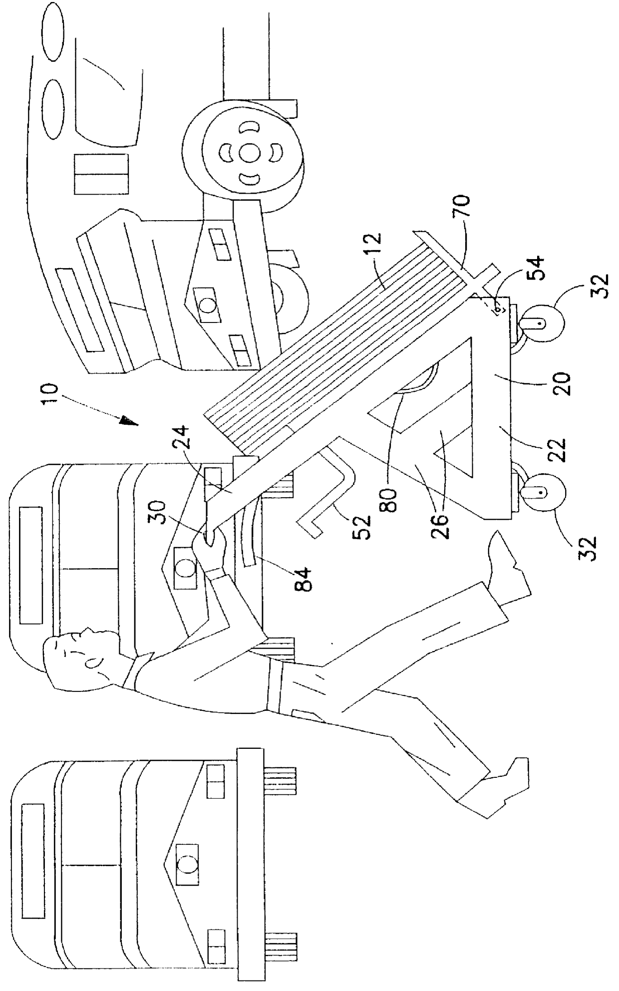
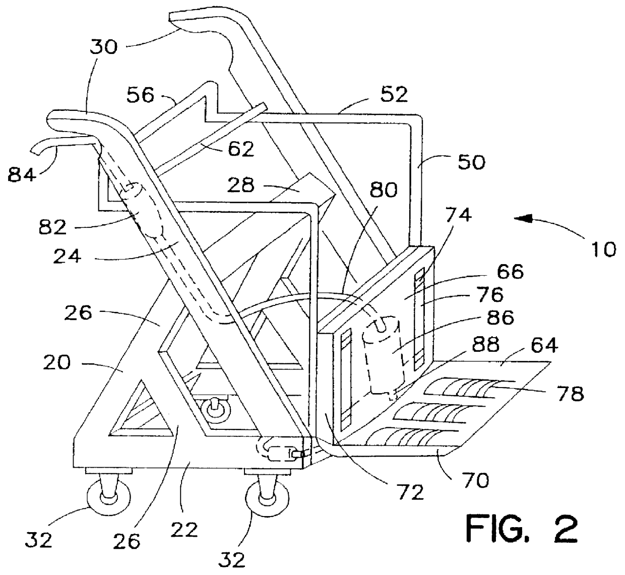
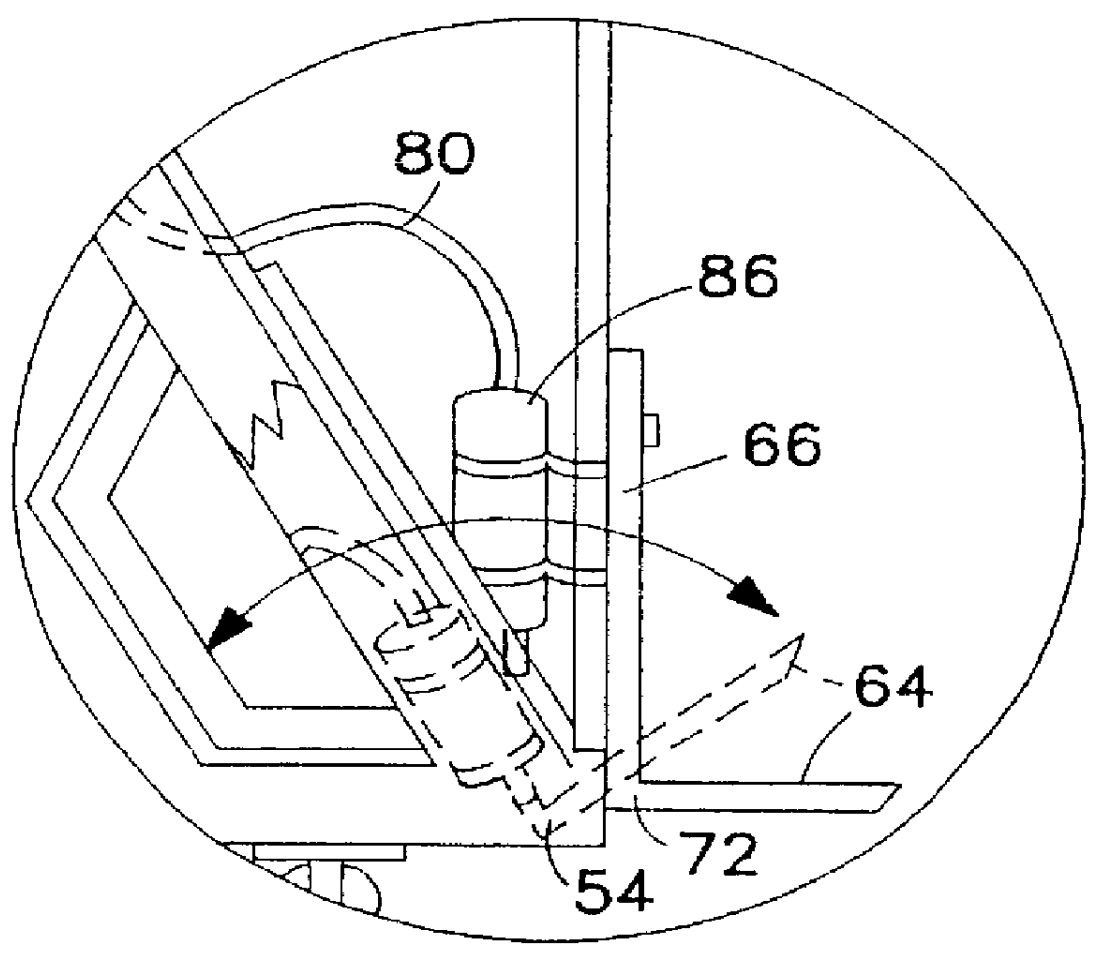
Referring to FIGS. 1-8, a caddy apparatus 10 for lifting and carrying heavy bus and truck tires 12 is disclosed. Apparatus 10 includes a cart frame 20 connected to a pivoting wheel maneuvering structure 50 having a hydraulically operated lift carriage 72.

Cart frame 20 is constructed of metal structural members forming a square horizonal frame base 22, handle members 24 extending upwardly and rearwardly from either side of frame base 22, first and second frame trusses 26 extending upwardly from frame base 22 to each handle member 24, and a cross strut 28 interconnecting the handle members 24 midway along their length. The frame base 22 is supported on four bearing mounted cart frame wheels 32, two of which are pivotally mounted to facilitate steering the apparatus 10.

Wheel maneuvering structure 50 includes a tilt frame 52 pivotally mounted to a tilt frame pivot bar 54 connected to the front of the frame base 22. Tilt frame 52 extends vertically upward such that it raises a wheel cent...


PUM

PropertyMeasurementUnit
heightaaaaaaaaaa
hydraulic poweraaaaaaaaaa
stabilityaaaaaaaaaa

Abstract

A caddy apparatus for lifting and carrying a vehicle tire includes a cart frame and a wheel maneuvering structure having a tilt frame and lift carriage slideably mounted on the tilt frame; a pivot mounting of the tilt frame on the cart frame; a tire lift carriage slideably mounted to the tilt frame of the wheel maneuvering structure for engaging and retaining a vehicle tire; and a tire lift carriage lifting and lowering mechanism, preferably employing a hydraulic pump and cylinder.

Description

1. Field of the InventionThe present invention relates generally to the field of motor vehicle servicing and repair equipment. More specifically the present invention relates to a caddy apparatus for lifting and carrying vehicle wheels and tires, particularly bus and truck tires, typically while the tires are mounted on wheels. The apparatus includes a cart frame and a wheel maneuvering structure pivotally mounted to the cart frame to pivot from a canted position to a substantially vertical position and vice versa. The wheel maneuvering structure includes a hydraulically operated tire lift carriage.The cart frame is preferably constructed of metal structural members forming a horizonal frame base on wheels and forming handle members extending upwardly and rearwardly from either side of the frame base. The handle members are conveniently placed to the left and right of the user. The wheel maneuvering structure includes a tilt frame pivotally mounted at the front of the frame base. Th...

Claims


Application Information

Patent Timeline
Patent Type & Authority Patents(United States)
IPC IPC(8): B60B29/00
CPCB60B29/002Y10T29/49819Y10T29/53539
Inventor GARNETT, WINFIELD J.
Owner GARNETT WINFIELD J
Why Eureka
Try Eureka