Radiation processing apparatus and method

a processing apparatus and a technology of irradiation, applied in the direction of milk preservation, meat/fish preservation by irradiation/electric treatment, milk preservation, etc., can solve the problems of slow and inefficient ribbon blender method, non-uniform irradiation and cooling, so as to achieve faster and more uniform production of irradiated chip polymers, the effect of faster air grinding

Inactive Publication Date: 2000-08-01
DREYER MARY E +4
View PDF4 Cites 43 Cited by
  • Summary
  • Abstract
  • Description
  • Claims
  • Application Information

AI Technical Summary

Benefits of technology

It is an object of the present invention to provide an apparatus and method for faster and more uniform production of irradiated chip polymers and faster air grinding.
It is a further object of the invention to easily adapt the apparatus and method employed for polymer irradiation, to the irradiation of food.

Problems solved by technology

The methods currently in practice to irradiate polymers including but not limited to polytetrafluorethylene (PTFE), are batch processes, which are slow and result in non-uniform irradiation and cooling.
But despite the use of multiple passes, this tray method is slow and inefficient, and results in some non-uniform irradiation and cooling.
The ribbon blender method is slow and inefficient because of time consumed in loading and unloading the blender.
Further, because it is common to process recycled PTFE scrap from numerous sources where the specifications, including density, vary widely, the radiation dosage is non-uniformly applied, particularly where the polymer chips are of differing densities and heavier chips tend to seek the bottom of the blender and resist complete agitation.
The ribbon blender method also suffers from only random exposure of chips to the cooling surface of the blender shell, and thus, non-uniform cooling.
In short, the prior art methods are slow, chips are not uniformly radiated, and they are not uniformly cooled.
Additionally, there have been a number of instances in which people have become ill or even died from consuming contaminated meats.

Method used


Image

  • Radiation processing apparatus and method
  • Radiation processing apparatus and method
  • Radiation processing apparatus and method

Examples


Embodiment Construction

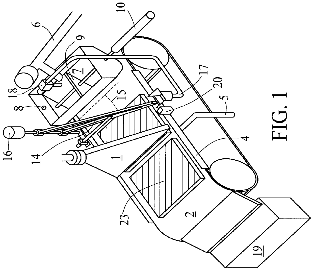
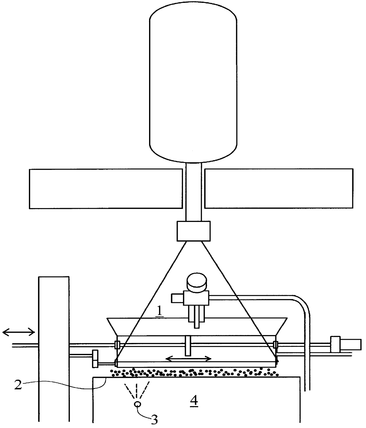
FIGS. 1 and 2, respectively, are perspective and end views of an apparatus for processing material in accordance with the present invention. The apparatus is useful for radiation cross linking of polymers in order to render a polymer, particularly PTFE, suitable for air grinding into fine powder. In the form of powder PTFE has many uses ranging from frying pans to lubricants.

The apparatus is located within a masonry vault (not shown) to contain ozone and stray radiation, and both the inlet to the system and the outlet are isolated from areas occupied by personnel by means of rotary iron valves (not shown), known commercially as "Rotoloks."

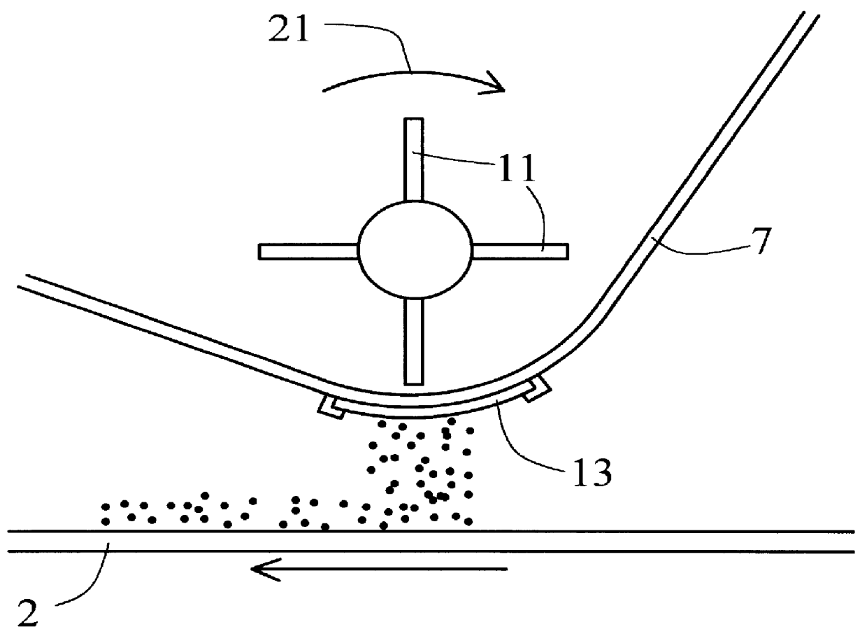
Unradiated chips are fed by auger 6 into chip feed hopper 7, passing over a magnetic separator (not shown) to remove undesired "tramp iron." A hopper level sensor 8 for detecting when the chips have reached a certain level, controls the motor of auger feed 6 so as to prevent overflowing feed hopper 7. This level sensor may be a photocell, or any ot...


PUM

PropertyMeasurementUnit
sizeaaaaaaaaaa
widthaaaaaaaaaa
angleaaaaaaaaaa

Abstract

A method and apparatus for the continuous feeding of polymer chips or particles to an electron beam accelerator makes use of spreading, belt conveying, irradiation and cooling. The apparatus is designed to make more efficient use of radiation through continuous feed. This method and apparatus, suitably adapted, is also used for food irradiation and decontamination, particularly for ground meats.

Description

This invention relates to continuous radiation treatment for cross linking and degradation of polymers including but not limited to cross linking of polytetrafluorethylene (PTFE), as well to similar radiation treatment for meat decontamination.The purpose of radiation crosslinking for solid polymers is to facilitate air fluidized bed grinding of the subject polymer to a fine powder. Many polymers, including PTFE, can only be ground by using an air jet mill in fluidized bed form. The more uniform the radiation dosage, the faster grinding can proceed. In addition, irradiation is most efficient if the polymer temperature during irradiation can be maintained below a predetermined maximum temperature.The methods currently in practice to irradiate polymers including but not limited to polytetrafluorethylene (PTFE), are batch processes, which are slow and result in non-uniform irradiation and cooling. Dillon (U.S. Pat. No. 3,766,031) teaches the use of trays containing chips which make mul...

Claims


Application Information

Patent Timeline
Patent Type & Authority Patents(United States)
IPC IPC(8): A23B4/06A23B4/00A23B4/015B29C31/00B29C31/02B29B13/00B29B13/08B29C35/16B29C35/08B29C35/00C08F2/46
CPCA23B4/015A23B4/062B29B13/08B29C31/02B29C2035/0877B29C2035/1616B29K2027/18B29K2105/251
Inventor ECKHOFF, PAUL S.
Owner DREYER MARY E
Why Eureka
Try Eureka