Automatic image quality adjustment device adjusting phase of sampling clock for analog video signal to digital video signal conversion
an image quality adjustment and phase adjustment technology, applied in the field of automatic image quality adjustment devices, can solve problems such as inability to detect the optimum phase, liquid crystal display devices which give no consideration to periodical automatic adjustment, and cannot cope with changes
- Summary
- Abstract
- Description
- Claims
- Application Information
AI Technical Summary
Problems solved by technology
Method used
Image

Examples
first modification
(First Modification)
The above-mentioned process for detecting the image quality judgement data in the image quality detector portion 7 determines the data about the absolute values of the differences throughout the single frame and thereafter detects the maximum one of the absolute values. If the input video signal V0 contains noises, the influence of the noises increases the data about the absolute values of the differences, decreasing the reliability of the detected data.
An alternative to the above-mentioned detecting process may use the averages of all difference data within one frame as the image quality judgement data. This reduces the influence of the noises, but loses the advantage of the above-mentioned detecting process that a smaller memory area is required to store the difference data in the image quality detector portion 7.
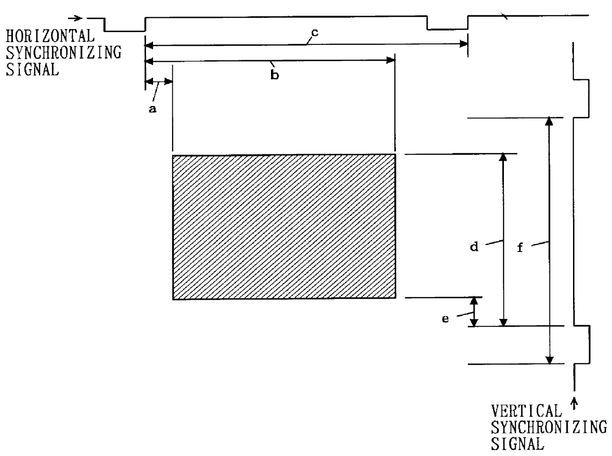
Another modification may be employed which defines a particular region (e.g., a central square region including a 50 by 50 matrix of pixels) within on...
second modification
(Second Modification)
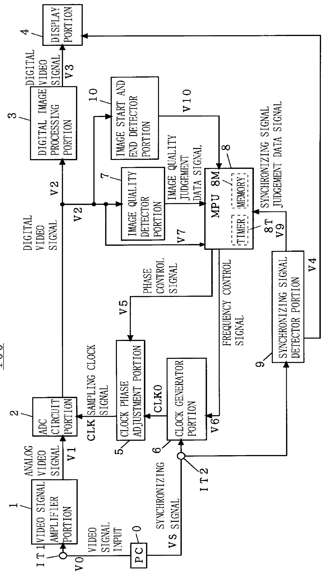
In the first preferred embodiment, the image quality judgement data are obtained, with the sampling clock phase changed for each frame. For increase in detection rate, a picture within one frame may be divided into several (n) blocks arranged in the vertical direction during only the phase detection with reference to FIG. 7, and image quality detector portions 71 to 7n and clock phase adjustment portions 51 to 5n may be provided respectively for the blocks Bm so that a different phase is set for each block Bm as shown in the block diagram of FIG. 8. Such a configuration of a display device 100A allows the processing of one-frame video data to provide the phase changes for several steps and a plurality of image quality judgement data for the phase changes at one time.
Thus, the second modification is adapted to divide one picture within one frame into n blocks for which the separate clock phase adjustment portions 51 to 5n are provided respectively so that the dif...
third modification
(Third Modification)
A third modification is applicable to the first preferred embodiment and the first and second modifications thereof.
In accordance with the above description, the sampling clock frequency is determined by the standard image signal timing data previously stored in the MPU 8, based on the data detected about the frequency and polarity of the synchronizing signal by the synchronizing signal detector portion 9 and the data detected by the image start and end detector portion 10.
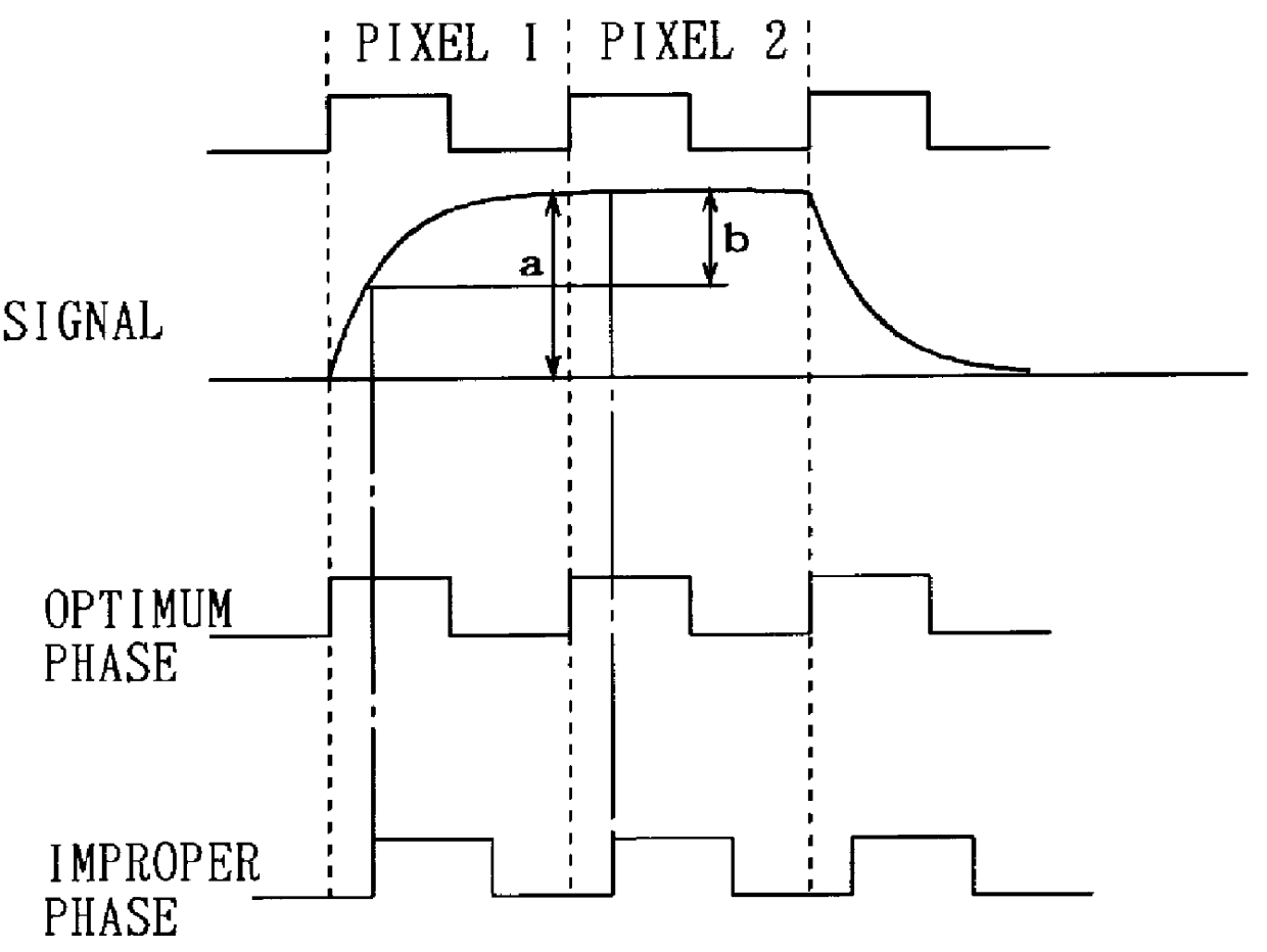
However, the MPU 8 is capable of determining the sampling frequency without using the detection signals V9 and V10 and the standard video signal timing data. Specifically, if the sampling frequency is not optimum, the comparison data immediately preceding and following the difference data are increased or decreased with changes in sampling clock phase. The cycle of this fluctuation depends on the amount of shift of the sampling frequency from its optimum value. Then, the MPU 8 sets the sampling...
PUM
 Abstract
Description
Claims
Application Information
 - Generate Ideas
- Intellectual Property
- Life Sciences
- Materials
- Tech Scout
- Unparalleled Data Quality
- Higher Quality Content
- 60% Fewer Hallucinations
Browse by: Latest US Patents, China's latest patents, Technical Efficacy Thesaurus, Application Domain, Technology Topic, Popular Technical Reports.
© 2025 PatSnap. All rights reserved.Legal|Privacy policy|Modern Slavery Act Transparency Statement|Sitemap|About US| Contact US: help@patsnap.com