

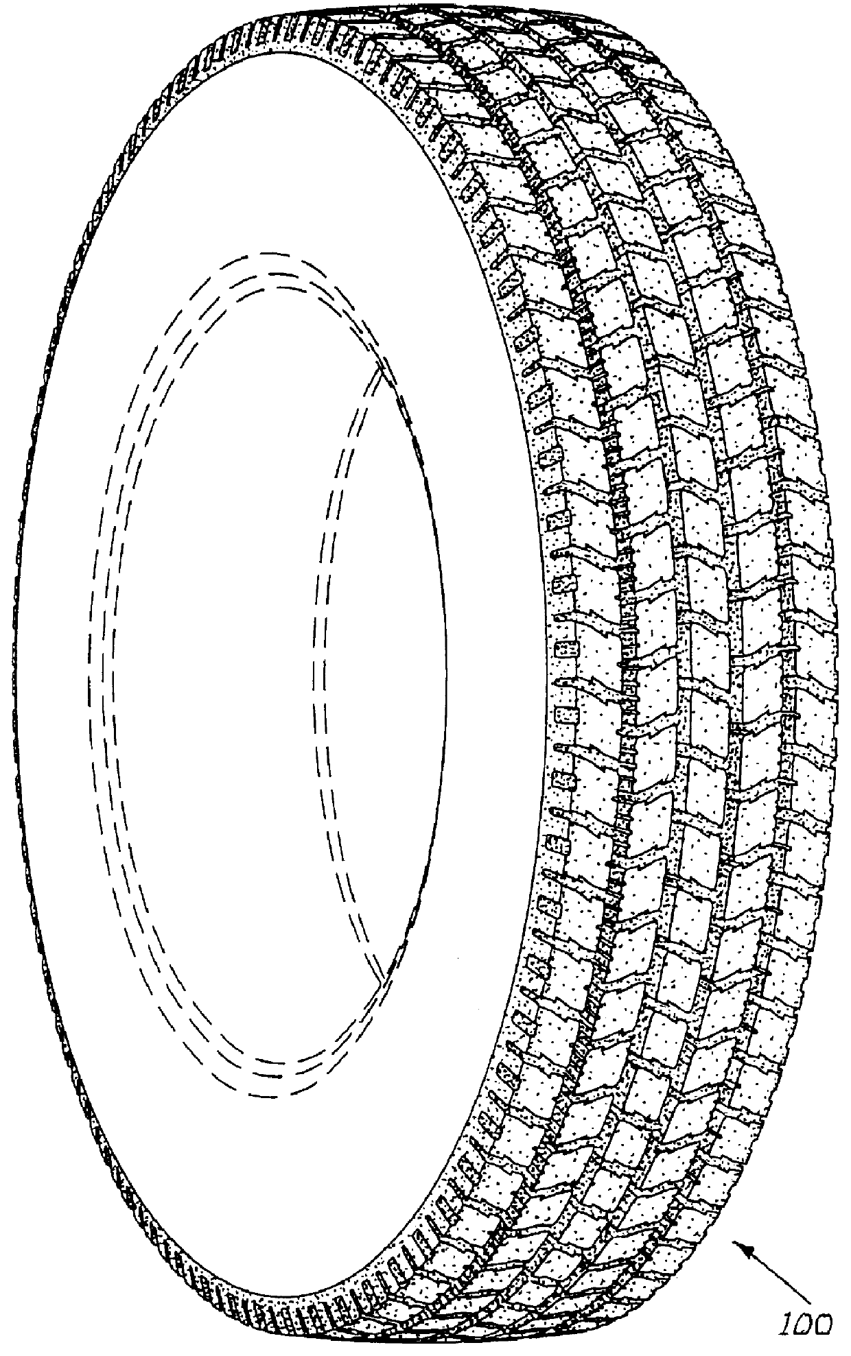
Tire having sacrificial bridging
a technology of sacrificial bridging and tire, which is applied in the direction of vehicle components, transportation and packaging, non-skid devices, etc., can solve the problems of tire removal from service, user dissatisfaction, and uneven tread surfa
- Summary
- Abstract
- Description
- Claims
- Application Information
AI Technical Summary
Problems solved by technology
Method used
Image

Examples
first embodiment
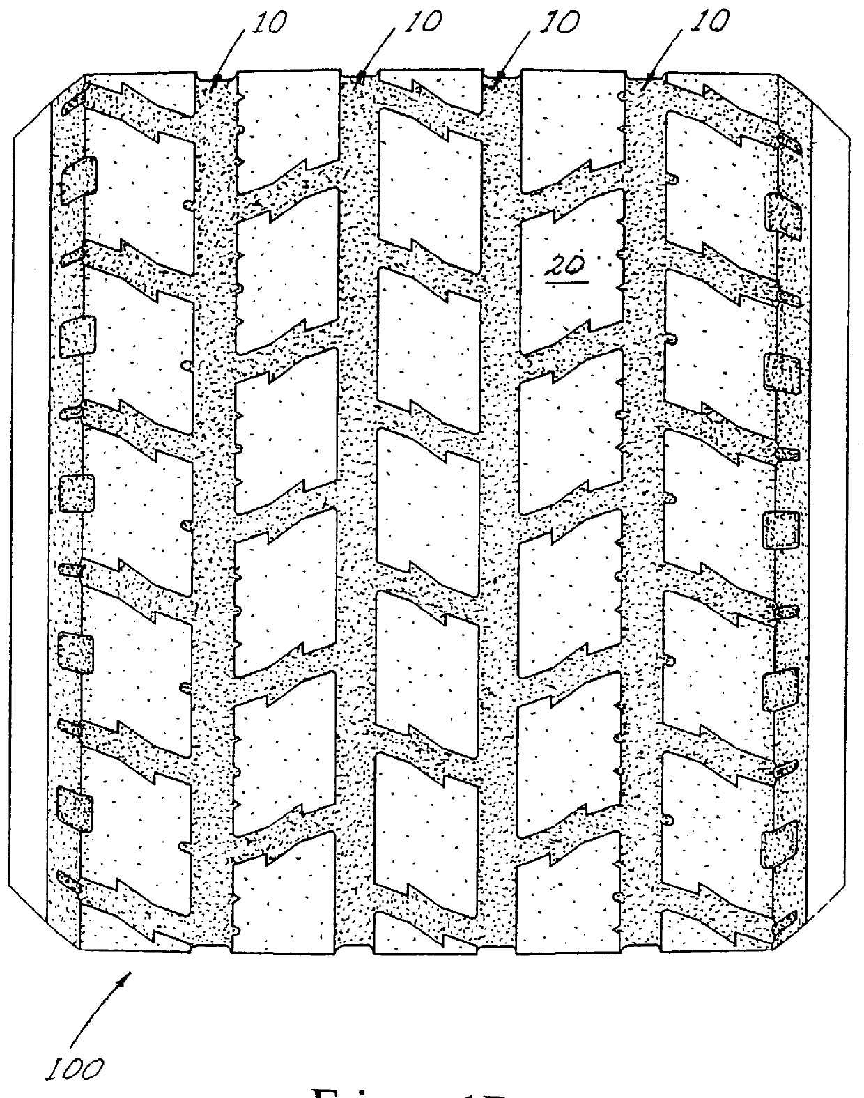
The invention disclosed herein can be advantageous for all classes of pneumatic tires where there is a need to improve the compromise between traction capabilities and overall service life. In order to demonstrate the improvements possible with the present invention, three different designs according to this first embodiment were prepared on 275 / 80 R 22.5 heavy duty truck radial tires and then were mounted on the drive axles of 6.times.4 heavy duty trucks operated under highway service conditions. Each design was mounted with a companion set of prior art tires. During the course of the test, tread depths and tread surface profiles were measured as well as notations of the appearance of tread surface anomalies. The specifics of the three designs and the prior art reference tire are shown in Table 1.
From the results of these tests, a tire according to the invention described by this embodiment could maintain an acceptable recess and thus d / h for up to 144,000 km (90,000 miles). The re...
second embodiment
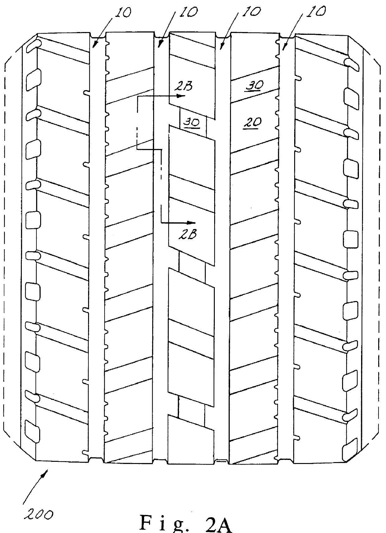
the invention is shown in FIGS. 4a and 4b wherein cuts 40 and 50 may be inclined with respect to the outward normal from the tread surface. In these cases the axes of the cuts 40 and 50 have inclination angles .alpha..sub.1 and .alpha..sub.2, respectively, relative to the outward normal from the tread surface. Angle .alpha. is positive when the groove axis is rotated in the direction of tire rotation or counterclockwise as shown in FIGS. 4a and 4b. In the first example shown in FIG. 4a only cut 40 is inclined in the range -15.degree..ltorsim..alpha..sub.1 .ltorsim.-5 and preferably .alpha..sub.1 is approximately -10.degree.. In another example (not shown) only cut 50 is inclined in the range -15.degree..ltorsim..alpha..sub.2 .ltorsim.-5 and preferably .alpha..sub.2 is approximately -10.degree.. For the example shown in FIG. 4b, both cuts 40 and 50 are inclined and .alpha..sub.1 and .alpha..sub.2 have negative values. In the example of FIG. 4b, inclination of the grooves can be effec...
PUM
 Abstract
Description
Claims
Application Information