Two-phase or mono-phase heat exchanger for electronic power component

Inactive Publication Date: 2000-08-15
FERRAZ DATE IND
View PDF12 Cites 104 Cited by
  • Summary
  • Abstract
  • Description
  • Claims
  • Application Information

AI Technical Summary

Benefits of technology

Thanks to the invention, the rigid plate of the heat-exchange unit forms a self-supporting structure for the heat-exchanger, which makes it possible to dispense with the systematic use of a chassis.
According to another advantageous aspect of the invention, the plate has, on at least one of its principal faces, means for fixing electronic power components of various shapes and in variable number. This aspect of the invention makes it possible, with the aid of one type of plate, to accommodate several types of electronic components, which makes it possible substantially to reduce the reference number of plates capable of belonging to heat-exchange units with respect to the devices of the prior art. In particular, it may be provided that these fixing means be tappings distributed on at least one of the principal faces of the plate or plates.

Problems solved by technology

In that case, with the known device, it is necessary to provide a chassis supporting the bank of heat-exchangers, which substantially increases the cost of an installation.
This induces the creation of a large number of references of heat-exchange units, rendering manufacture and maintenance of the groups of heat-exchangers more complex.

Method used


Image

  • Two-phase or mono-phase heat exchanger for electronic power component
  • Two-phase or mono-phase heat exchanger for electronic power component
  • Two-phase or mono-phase heat exchanger for electronic power component

Examples


Embodiment Construction

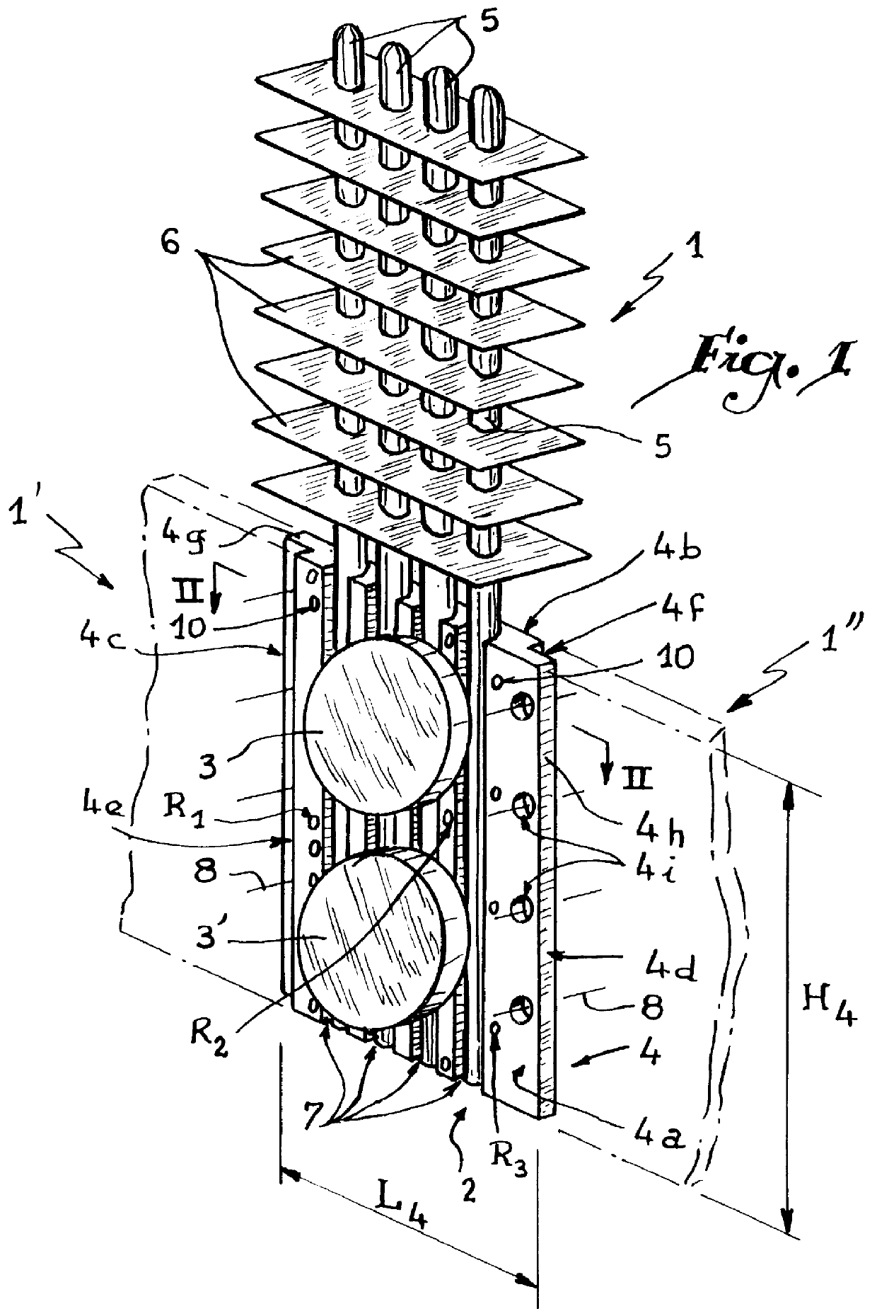
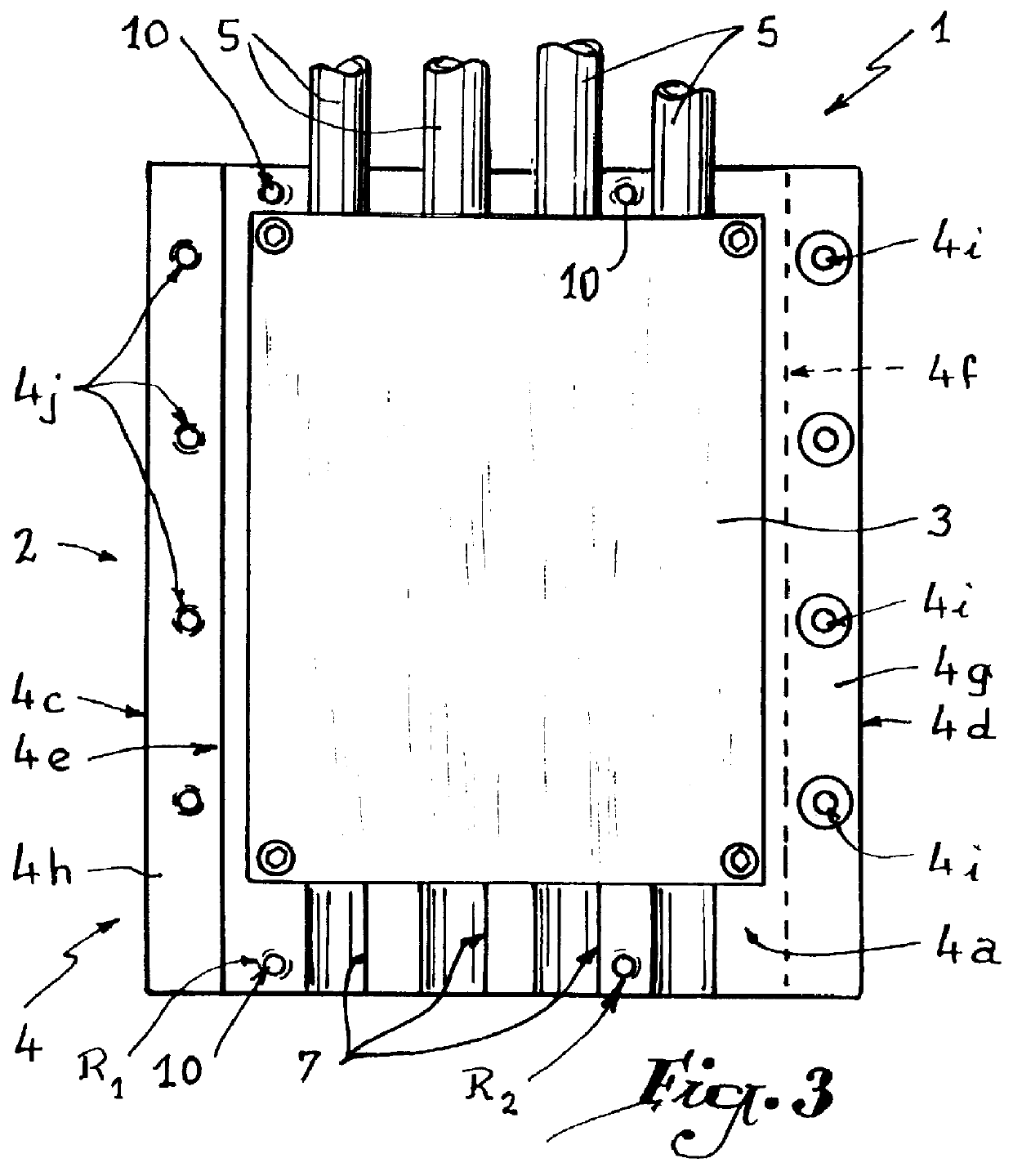
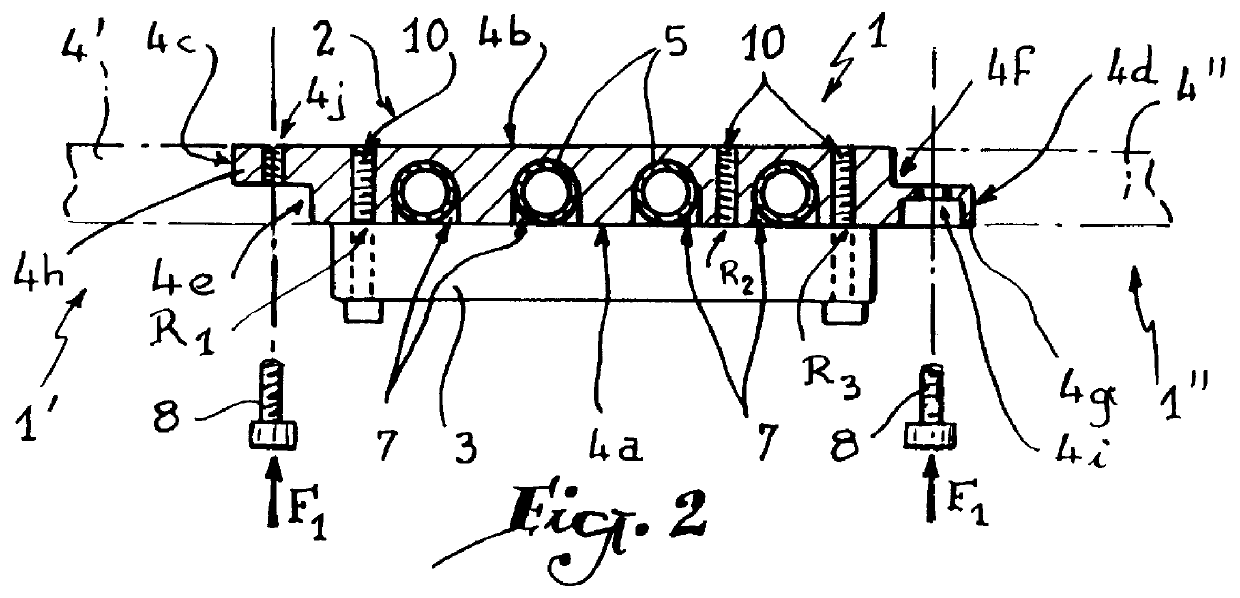
Referring now to the drawings, and firstly to FIG. 1, three identical heat-exchangers 1, 1' and 1" are shown, exchangers 1' and 1" being simply silhouetted in dashed and dotted lines. Heat-exchanger 1 comprises a unit 2 adapted to receive two electronic components 3 and 3' such as IGBT circuits or equivalent. Unit 2 is essentially composed of an aluminium plate 4 on which are connected tubes 5 for evaporation and condensation of a heat-exchanging liquid such as methanol or water. In the part which projects from unit 2, the tubes 5 are provided with cooling fins 6 allowing dissipation of the heat.

The operational principle is as follows: the heat released by components 3 and 3' has for its effect to increase the temperature of the unit 2, this leading to an evaporation of the liquid located in the lower part of the tubes 5 inside parallel grooves 7 for receiving this lower part of the tubes. The vapour formed in the lower part of the tubes circulates upwardly inside each tube 5. As th...


PUM


Abstract

A two-phase or mono-phase heat-exchanger for at least one electronic power component wherein the heat-exchanger supports a plurality of heat exchange tubes, each having a heat exchange fluid therein, and wherein said heat-exchanger includes at least one rigid plate provided with zones for receiving portions of the heat exchange tubes and wherein the heat-exchanger includes opposite edges which are formed so as to be secured to edges of adjacent heat-exchangers in such a manner that front and rear surfaces of the at least one rigid plate of each heat exchange unit are coplanar when one heat-exchanger is secured to an adjacent heat-exchanger.

Description

The present invention relates to a two-phase or mono-phase heat-exchanger for electronic power components.BRIEF STATEMENT OF THE RELATED ARTHeat-exchangers of this type are necessary in order to avoid damaging overheating of electronic power components such as IGBT (Insulated Gate Bipolar Transistor) circuits or equivalent. A heat-exchanger comprising a plurality of tubes for evaporation / condensation of a heat-exchanging liquid and a block forming a heat-exchange unit with an electronic component is described in European Patent Application 0 417 299. Furthermore, WO-A-95 / 17765 discloses a heat-exchanger essentially constituted by a plate provided with grooves for receiving tubes for circulation of a heat-exchanging liquid.Heat-exchangers of this type are generally installed as a bank in order to cool a consequent number of electronic components of various dimensions. In that case, with the known device, it is necessary to provide a chassis supporting the bank of heat-exchangers, whi...

Claims


Application Information

Patent Timeline
IPC IPC(8): H01L23/34H01L23/427F28D15/02
CPCF28D15/0275H01L23/427F28F1/20F28F1/32H01L2924/0002H01L2924/00
Inventor JULIEN, JEAN-NOELLACHISE, JACQUES
Owner FERRAZ DATE IND
Why Eureka
Try Eureka