Method and device for fuel injection for engines

a fuel injection and engine technology, applied in the direction of machines/engines, electric control, speed sensing governors, etc., can solve the problems of high cost, high cost, and inability to meet the rapid reduction of target pressure, so as to achieve the effect of reducing the cost of fuel injection

Inactive Publication Date: 2000-08-22
ISUZU MOTORS LTD
View PDF8 Cites 39 Cited by
  • Summary
  • Abstract
  • Description
  • Claims
  • Application Information

AI Technical Summary

Benefits of technology

With this fuel injection method, when the pressure condition is met whereby the actual pressure of the common rail is higher than the target pressure by more than a predetermined value, the amount of fuel to be injected from the injectors is set to the second fuel injection amount which is less than the first fuel injection amount that stabilizes the engine revolution speed during the no-load operation. This ensures reduction in the engine revolution speed. The second fuel injection amount is equal to the first fuel injection amount (which may be constant or varies with the revolution speed) multiplied by a factor of less than one. Because the fuel corresponding to the second fuel injection amount continues to be supplied from the common rail to the injectors where it is consumed for injection, the common rail pressure can be reduced reliably. Hence, when the accelerator is operated next to perform positive fuel injections, the fuel can be prevented from being injected at abnormally high common rail pressure or fuel injection pressure, thus avoiding degradation of the exhaust emission characteristics.
When the pressure condition is met and also the injection amount condition is met whereby the basic fuel injection amount is less than the second fuel injection amount, the amount of fuel to be injected from the injectors is set to the second fuel injection amount. When, with the pressure condition met, the basic fuel injection amount is very small, less than the second fuel injection amount, the amount of fuel to be injected increases slightly to the second fuel injection amount. An increase in the amount of fuel supplied from the common rail therefore swiftly reduces the common rail pressure.

Problems solved by technology

Under a transient state where the common rail target pressure is not constant, however, the exhaust emission performance may deteriorate unless an appropriate pressure control is provided.
That is, in the common-rail type fuel injection device, although raising the fuel injection pressure can easily be done by raising the common rail pressure by operating the control valve of the fuel pump, the common rail pressure cannot be lowered except by fuel injection from the injectors or by leaking fuel from the injection system such as common rail.
However, the actual common rail pressure cannot follow the rapid reduction in the target pressure and remains high.
Further, the fuel cannot be expected to leak within a short period of time from an injection system ranging from the common rail to the injectors.
The rapid pressure reduction system in the common rail, however, requires a relief valve and a relief pipe for pressure reduction, increasing the number of parts and therefore the cost of the fuel injection control device.
Further, when the pressure condition is met, the fuel injection timing at which to inject fuel from the injectors is delayed from an injection timing used when the pressure condition is not met.
Therefore, a large amount of fuel can be injected even during a shorter injection period.
Because injection of a large amount of fuel at an early stage in the fuel injection period can cause undesired phenomena in terms of engine characteristics such as knocking, the fuel injection timing is delayed.

Method used


Image

  • Method and device for fuel injection for engines
  • Method and device for fuel injection for engines
  • Method and device for fuel injection for engines

Examples


Embodiment Construction

One embodiment of the fuel injection method and device for engines according to this invention will be described by referring to the accompanying drawings.

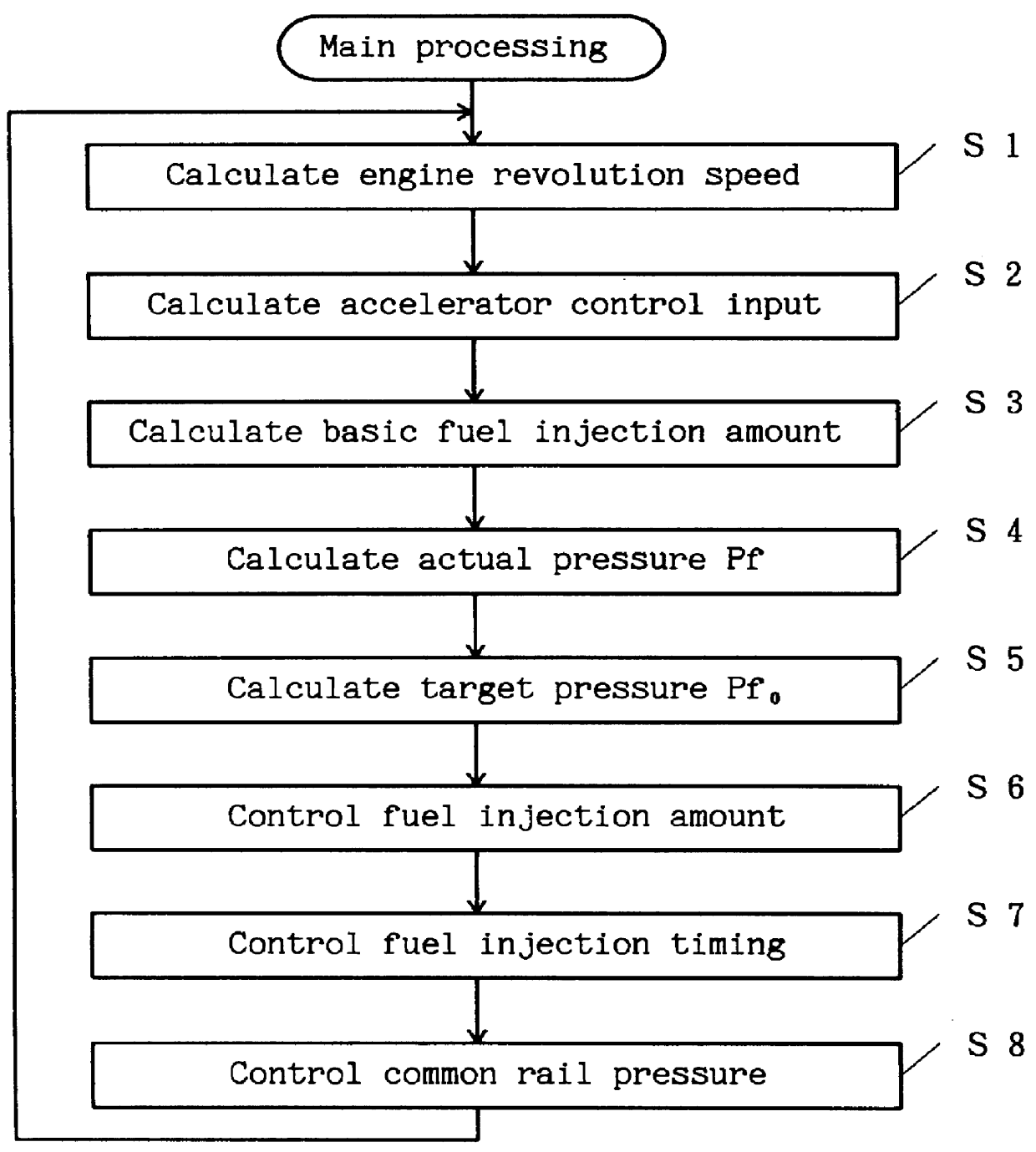
Let us first explain about the main routine shown in FIG. 1. This routine is in practice executed during an interrupt processing. This embodiment applies to the common-rail type injection system shown in FIG. 5.

(1) An engine revolution speed Ne is calculated by using pulses generated by the rotation of the output shaft of the engine (the pulses may be detected by a pickup sensor accessing the teeth of a gear secured to the output shaft) (step S1).

(2) An accelerator control input Acc is calculated from signals detected by an accelerator opening sensor (for example, an accelerator pedal depression amount sensor) (step S2).

(3) A basic fuel injection amount Qb is calculated based on the engine revolution speed Ne calculated by step S1 and the accelerator control input Acc calculated by step S2 (step S3). The engine revolution speed Ne...


PUM


Abstract

The common-rail type fuel injection method of this invention injects a small amount of fuel during the deceleration of engine to swiftly accomplish reductions in the common rail pressure and the engine revolution speed, thus reducing the amount of NOx at the end of the deceleration. The basic fuel injection amount Qb is determined from the accelerator control input Acc and the engine revolution speed Ne (step S10). When the actual pressure Pf of the common rail is higher than the target pressure Pf0 by more than a predetermined value alpha (step S11) and also the basic fuel injection amount Qb is smaller than the second fuel injection amount, which is equal to a smaller-than-one factor k times the first fuel injection amount Qpd that stabilizes the engine revolution speed during no-load operation (step S12), then the final fuel injection amount Qfin is set to the second fuel injection amount (step S13) to lower the common rail pressure in order to avoid fuel injection at high pressure when the accelerator is depressed again.

Description

1. Field of the InventionThe present invention relates to a method and device for controlling a common rail pressure in a common-rail type fuel injection system.2. Description of the Prior ArtAs for the fuel injection control in engines, a common-rail type fuel injection system has been known which provides a high injection pressure and performs optimum control on injection characteristics, such as fuel injection timing and the amount of fuel injected, according to the operating condition of the engine. The common rail type fuel injection system is a fuel injection system that stores in the common rail a fuel pressurized to a predetermined pressure by a pump and then injects the stored fuel from injectors into corresponding combustion chambers. To ensure that the pressurized fuel will be injected from each injector under optimum injection conditions according to the engine operating conditions, a controller controls the fuel pressure in the common rail and the operation of control v...

Claims


Application Information

Patent Timeline
Patent Type & Authority Patents(United States)
IPC IPC(8): F02D41/12F02D41/38F02D41/04F02M37/08F02D41/34F02D41/40F02M47/02F02M59/20
CPCF02D41/12F02D41/3845F02D41/40F02D41/3872F02D2250/31Y02T10/44Y02T10/40
Inventor NISHIYAMA, YASUHIRO
Owner ISUZU MOTORS LTD
Why Eureka
Try Eureka