Method and apparatus for providing positive airway pressure to a patient

a positive airway pressure and patient technology, applied in the direction of valve details, valve arrangement, operating means/releasing devices of valves, etc., can solve the problems of exposing the patient to pressures that are higher, contributing to the collapse of the patient, and offering far from optimal therapy

Inactive Publication Date: 2000-08-22
RIC INVESTMENTS LLC
View PDF25 Cites 513 Cited by
  • Summary
  • Abstract
  • Description
  • Claims
  • Application Information

AI Technical Summary

Problems solved by technology

However, this approach exposes the patient to pressures that are higher than the pressures needed to support the airway for most of the breathing cycle.
This negative pressure acts upon the airway and contributes to its collapse.
Conventional CPAP is rather crude and offers far from optimal therapy since the CPAP pressure is based solely on a worst-case treatment parameter, i.e., the peak pressure requirements during inspiration.
Nevertheless, bi-level therapies also fail to afford optimal treatment because the inspiratory positive airway pressure (IPAP) of bi-level PAP is again based on the patient's peak needs encountered during inspiration and remains constant over the entire inspiratory phase respiration.
One of the problems with this mode of treatment, however, is that the patient has difficulty stopping inspiratory flow.
As the former pressure typically exceeds the latter, the "surplus" IPAP at the end of inspiration leads to uncomfortable and potentially harmful hyperinflation of the patient lungs.
As such, the administration of EPAP throughout the expiratory cycle to assure that satisfactory PEEP is maintained undesirably contributes to the breathing work that a patient must perform during exhalation.
Although effective for their intended purposes, this and other iron lung devices have generally fallen into disfavor because of their bulk, inconvenience, cost and limited application.
Further, iron lungs do not lend themselves to treatment of OSAS and related disorders where comfort and unobtrusiveness are critical for patient compliance and treatment efficacy.
A drawback to this system, however, is that a single resi

Method used


Image

  • Method and apparatus for providing positive airway pressure to a patient
  • Method and apparatus for providing positive airway pressure to a patient
  • Method and apparatus for providing positive airway pressure to a patient

Examples


Embodiment Construction

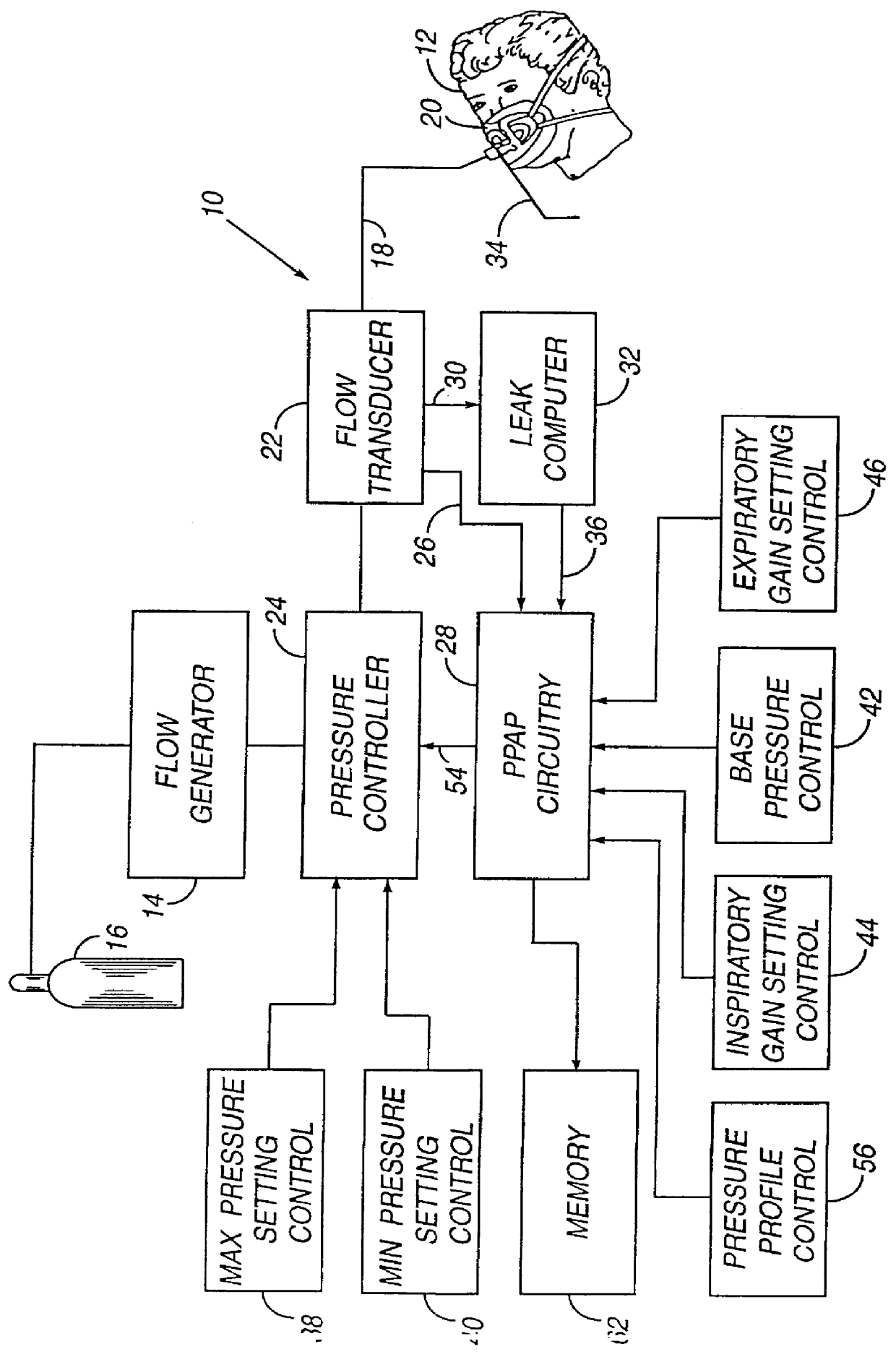
There is generally indicated at 10 in FIG. 1 a proportional positive airway pressure apparatus according to a presently preferred embodiment of the instant invention and shown in the form of a functional block diagram. Apparatus 10 is operable according to a novel process to deliver breathing gas, such as air, oxygen or a mixture thereof, at relatively higher and lower pressures (i.e., generally equal to or above ambient atmospheric pressure) to a patient 12 in proportion to the patient's respiratory flow for treatment of OSAS, COPD and other respiratory disorders.

Apparatus 10 includes a gas flow generator 14, such as a conventional CPAP or bi-level PAP blower, i.e., a centrifugal blower with a relatively steep pressure-flow relationship at any constant speed, that receives breathing gas from any suitable source, e.g., a pressurized bottle 16 of oxygen or air, the ambient atmosphere, or a combination thereof. The gas flow from flow generator 14 is passed via a delivery conduit 18 to...


PUM


Abstract

A system including methods and apparatus for treatment of a medical disorder such as obstructive sleep apnea or congestive heart failure. The system involves applying separate and independent gains to flow rates of pressurized gas delivered to a patient during inspiratory and expiratory phases of a respiratory cycle to deliver the pressurized gas in proportion to the respective gains during inspiration and expiration. A base pressure may be applied in addition to the gain-modified pressures and an elevated pressure profile may be employed to assist or control inspiration. The system may be fully automated responsive to feedback provided by a flow sensor that determines the estimated patient flow rate. A leak computer can be included to instantaneously calculate gas leakage from the system. The system may be utilized in connection with conventional continuous positive airway pressure (bi-level PAP) equipment to effect various beneficial treatment applications.

Description

1. Field of the InventionThe present invention relates generally to methods and apparatus for treating breathing and / or cardiac disorders and, more particularly, to methods and apparatus for providing a pressure to an airway of a patient during at least a portion of the breathing cycle to treat obstructive sleep apnea syndrome, chronic obstructive pulmonary disease, congestive heart failure, and other respiratory and / or breathing disorders.2. Description of the Related ArtDuring obstructive sleep apnea syndrome (OSAS), the airway is prone to narrowing and / or collapse while the patient sleeps. Continuous positive airway pressure (CPAP) therapy seeks to avoid this narrowing by supplying pressure to splint the airway open. With CPAP, this splinting pressure is constant and is optimized during a sleep study to be sufficient in magnitude to prevent narrowing of the airway. Providing a constant splinting pressure, i.e., CPAP, is a simple solution to the problem posed by the collapsing air...

Claims


Application Information

Patent Timeline
IPC IPC(8): A61M16/00A61M16/20
CPCA61M16/00A61M16/204A61M16/205A61M16/0066A61M2016/0021A61M2016/0036A61M2016/0039A61M16/0069A61M16/0051A61M16/024
Inventor ESTES, MARK C.MECHLENBURG, DOUGLAS M.FIORE, JOHN H.
Owner RIC INVESTMENTS LLC
Why Eureka
Try Eureka