Method and apparatus for providing positive airway pressure to a patient

a positive airway pressure and patient technology, applied in the direction of valve details, valve arrangements, life-saving devices, etc., can solve the problems of exposing the patient to pressures that are higher, contributing to the collapse of the patient, and offering far from optimal therapy

Inactive Publication Date: 2003-08-26
RIC INVESTMENTS LLC
View PDF20 Cites 293 Cited by
  • Summary
  • Abstract
  • Description
  • Claims
  • Application Information

AI Technical Summary

Benefits of technology

The control unit controls the pressure controller so that the breathing gas is delivered to the patient at a minimally sufficient pressure during at least a portion of a breathing cycle to perform at least one of the following functions at any given moment: (1) reduce cardiac preload and afterload, in which case the minimally sufficient pressure is a summation of a pressure needed to reduce cardiac preload and afterload in an absence of respiratory loading and a pressure needed to overcome an impact of respiratory loading on cardiac preload and afterload, and (2) prevent airway collapse, in which case the minimally sufficient pressure is a summation of a pressure needed to prevent airway collapse due to mechanical forces resulting from the structures of the patient and a pressure needed to overcome airway collapse due to respiratory effort. The apparatus also includes a selector unit that establishes a first gain. The control unit controls the pressure controller so as to deliver the breathing gas at the minimally sufficient pressure during at least a portion of the breathing cycle based on the first gain and the signal from the sensor.
It is a further object of the present invention to provide a modified CPAP apparatus that is capable of easily detecting exhalation and modifying the exhalation pressure to match a selected pressure profile. This object is achieved by providing an apparatus that includes a gas flow generator, a patient interface that couples the gas flow generator to the patient's airway, a sensor that detects a physiological condition that is suitable for use to differentiate between an expiratory phase and an inspiratory phase of a breathing cycle, a pressure controller that regulates the pressure of breathing gas provided to the patient, and a control unit that controls the pressure controller. More specifically, the control unit causes the breathing gas to be delivered at a first pressure level during an inspiratory phase of the breathing cycle, which is consistent with the operation of a conventional CPAP device. However, the control unit causes the breathing gas to be delivered in accordance with a predetermined pressure profile during the expiratory phase of the breathing cycle. This profile provides a decrease in the EPAP provided to the patient. Because the pressure profile can be obtained by controlling the operation of existing CPAP devices, it can be readily implemented on many such devices; thereby providing a better therapy for a patient using existing devices.
It is yet another object of the present invention to provide a system for eliminating oscillations in the flow provided during patient exhalation that can occur with use of the PPAP device. According to a first embodiment of the present invention, this object is achieved by causing the pressure controller to provide a pressure to the patient during expiration that is the greater of (1) a first minimally sufficient pressure that is determined by applying a gain to the signal output by the sensor and (2) a second minimally sufficient pressure that corresponds to a current pressure being provided to the patient. By ensuring that the pressure provided to the patient is always the greater of these two pressures, the pressure received by the patient during expiration does not oscillate, because should the pressure to be provided to the patient begin to decrease below the current pressure, the device will not use the calculated pressure, but will continue to provide the patient with the current pressure, thereby preventing a pressure decrease below the current pressure.
According to a second embodiment of the present invention, the object of preventing oscillations in the patient flow provided during expiration is achieved by causing the pressure controller to provide an expiration pressure that is determined based on a volume of gas to be exhaled and a gain. This gain can be the same gain or a different gain from that applied to the signal from the sensor during inspiration (if any). The volume of gas to be exhaled corresponds to a difference between the current volume of gas in the patient and the volume of gas in the patient at rest.

Problems solved by technology

However, this approach exposes the patient to pressures that are higher than the pressures needed to support the airway for most of the breathing cycle.
This negative pressure acts upon the airway and contributes to its collapse.
Conventional CPAP is rather crude and offers far from optimal therapy since the CPAP pressure is based solely on a worst-case treatment parameter, i.e., the peak pressure requirements during inspiration.
Nevertheless, bi-level therapies also fail to afford optimal treatment because the inspiratory positive airway pressure (IPAP) of bi-level PAP is again based on the patient's peak needs encountered during inspiration and remains constant over the entire inspiratory phase respiration.
One of the problems with this mode of treatment, however, is that the patient has difficulty stopping inspiratory flow.
As the former pressure typically exceeds the latter, the "surplus" IPAP at the end of inspiration leads to uncomfortable and potentially harmful hyperinflation of the patient lungs.
As such, the administration of EPAP throughout the expiratory cycle to assure that satisfactory PEEP is maintained undesirably contributes to the breathing work that a patient must perform during exhalation.
Although effective for their intended purposes, this and other iron lung devices have generally fallen into disfavor because of their bulk, inconvenience, cost and limited application.
Further, iron lungs do not lend themselves to treatment of OSAS and related disorders where comfort and unobtrusiveness are critical for patient compliance and treatment efficacy.
A drawback to this system, however, is that a single resistive gain is chosen for resistive loading or unloading.
Thus, a gain that may produce favorable results in regard to reducing breathing work during inspiration, for example, may cause less than desirable or even detrimental consequences during expiration.
Hence, to predict its ability to function in an open, leak-tolerant system would be problematic.
As such, whether it may be adapted to OSAS treatment, which invariably involves some degree of known and unavoidable unknown system leakage, is suspect.
Like the aforementioned Poon et al. device, however, the Ernst et al. apparatus relies upon an unduly complicated scheme dependent upon detected respiratory pressure and flow in calculating delivered output flow and pressure.
Additionally, apart from its utilization of two detected respiratory parameters (flow and pressure) and the complex manner in which these and other variables are reiteratively processed to produce apparatus flow and pressure output, the Ernst et al. system, although capable of delivering a base pressure equivalent to a patient's required end expiratory pressure, is nevertheless unable to deliver any pressure less than the base pressure.
Consequently, the Ernst et al. apparatus requires the patient to perform more breathing work than is necessary to satisfy his respiratory needs, especially in the expiratory phase of a respiration cycle, thereby deleteriously affecting the patient's comfort and likelihood of continued compliance with the treatment.
While conventional CPAP can help the heart rest, it has negative aspects for the patient such as increased work of exhalation and discomfort from the pressure.

Method used


Image

  • Method and apparatus for providing positive airway pressure to a patient
  • Method and apparatus for providing positive airway pressure to a patient
  • Method and apparatus for providing positive airway pressure to a patient

Examples


Embodiment Construction

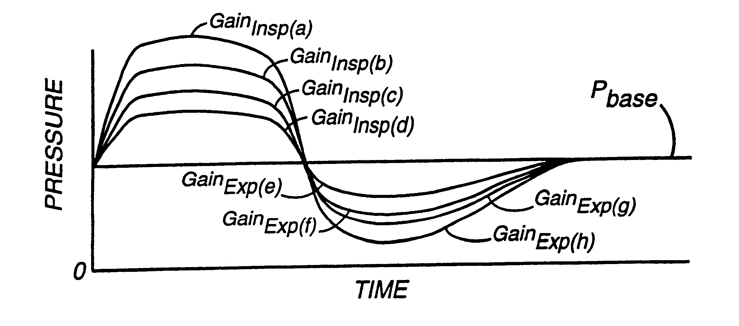
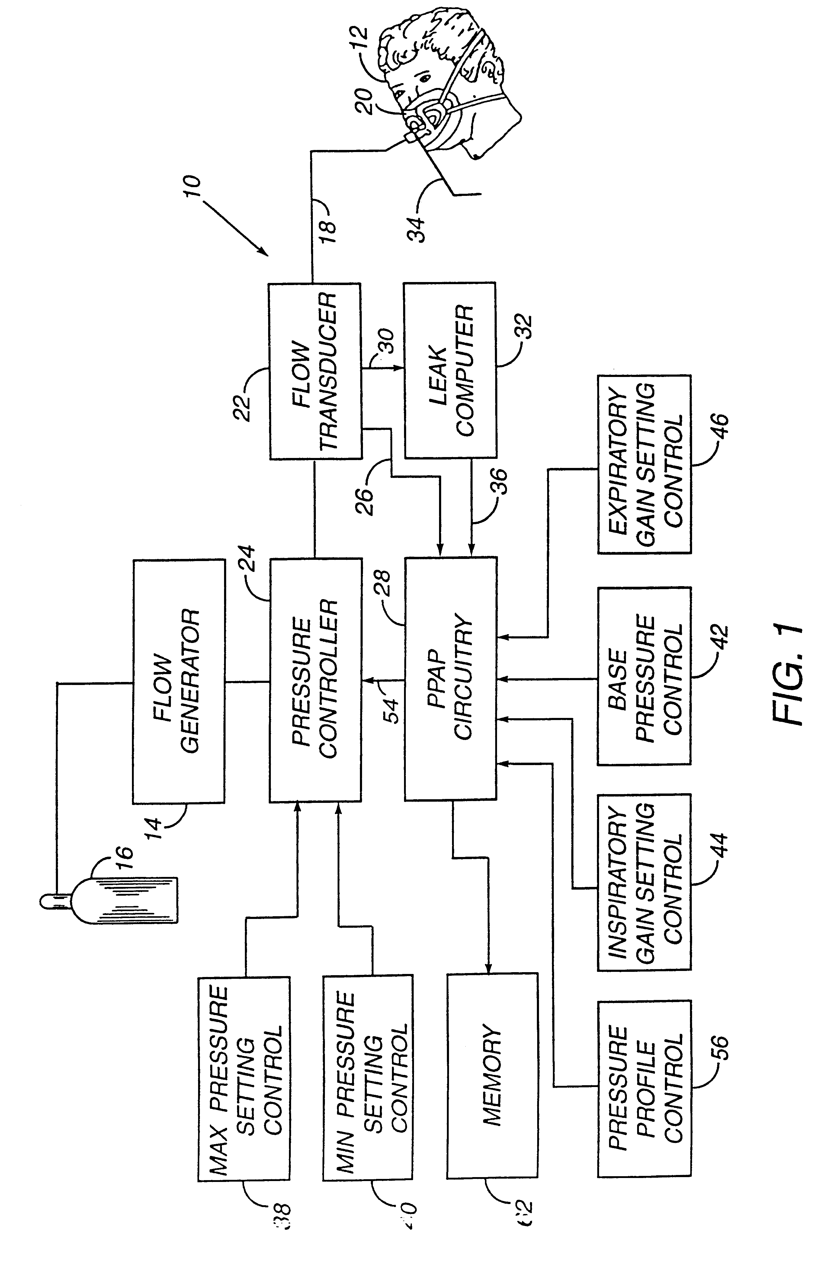
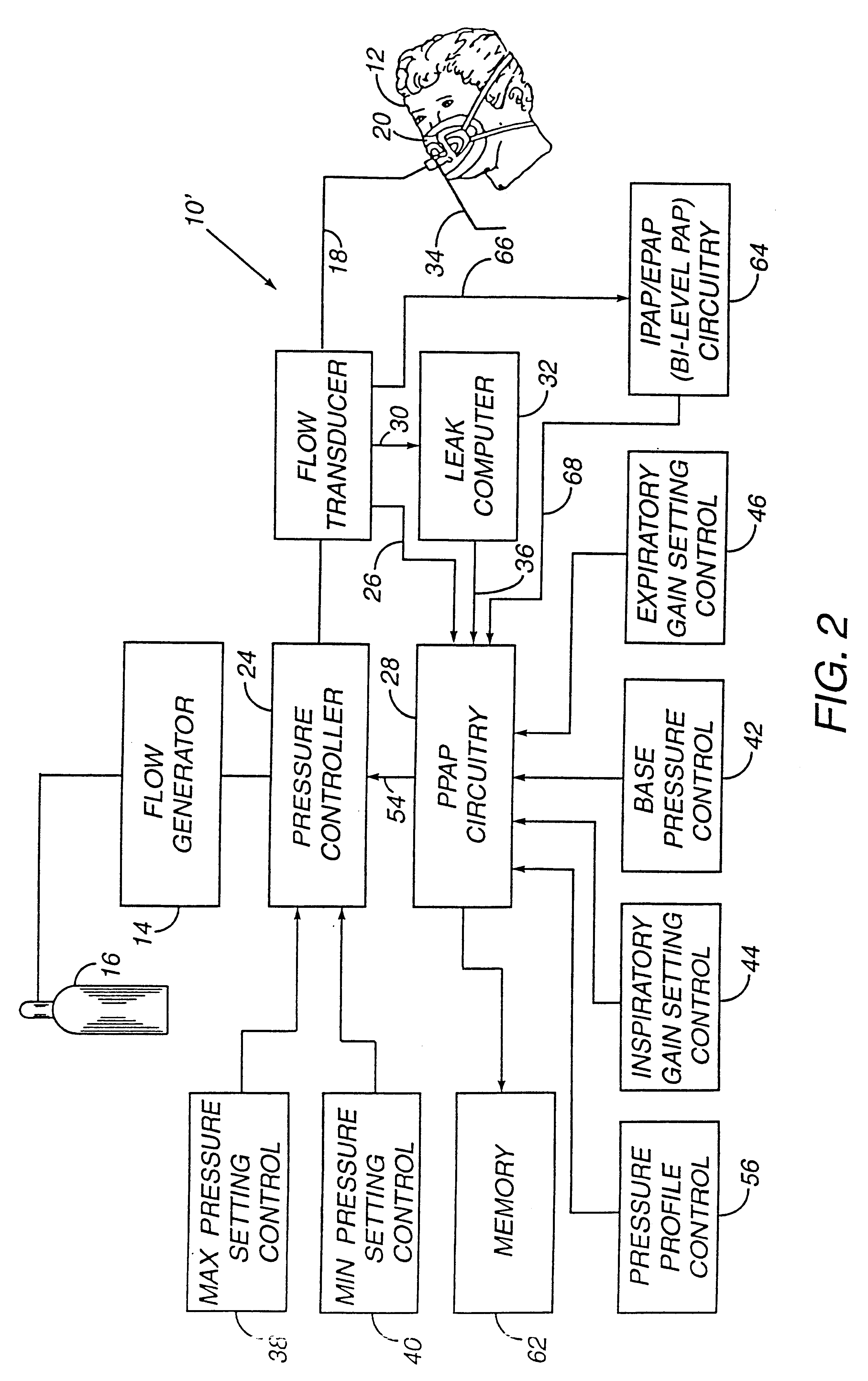
There is generally indicated at 10 in FIG. 1 a proportional positive airway pressure apparatus according to a presently preferred embodiment of the instant invention and shown in the form of a functional block diagram. Apparatus 10 is operable according to a novel process to deliver breathing gas, such as air, oxygen or a mixture thereof, at relatively higher and lower pressures (i.e., generally equal to or above ambient atmospheric pressure) to a patient 12 in proportion to the patient's respiratory flow for treatment of OSAS, COPD and other respiratory disorders.

Apparatus 10 includes a gas flow generator 14, such as a conventional CPAP or bi-level PAP blower, i.e., a centrifugal blower with a relatively steep pressure-flow relationship at any constant speed, that receives breathing gas from any suitable source, e.g., a pressurized bottle 16 of oxygen or air, the ambient atmosphere, or a combination thereof. The gas flow from flow generator 14 is passed via a delivery conduit 18 to...


PUM


Abstract

A system including methods and apparatus for treatment of a medical disorder such as obstructive sleep apnea or congestive heart failure. The system involves applying separate and independent gains to flow rates of pressurized gas delivered to a patient during inspiratory and expiratory phases of a respiratory cycle to deliver the pressurized gas in proportion to the respective gains during inspiration and expiration. A base pressure may be applied in addition to the gain-modified pressures and an elevated pressure profile may be employed to assist or control inspiration. The system may be fully automated responsive to feedback provided by a flow sensor that determines the estimated patient flow rate. A leak computer can be included to instantaneously calculate gas leakage from the system. The system may be utilized in connection with conventional continuous positive airway pressure (bi-level PAP) equipment to effect various beneficial treatment applications.

Description

1. Field of the InventionThe present invention relates generally to methods and apparatus for treating breathing and / or cardiac disorders and, more particularly, to methods and apparatus for providing a pressure to an airway of a patient during at least a portion of the breathing cycle to treat obstructive sleep apnea syndrome, chronic obstructive pulmonary disease, congestive heart failure, and other respiratory and / or breathing disorders.2. Description of the Related ArtDuring obstructive sleep apnea syndrome (OSAS), the airway is prone to narrowing and / or collapse while the patient sleeps. Continuous positive airway pressure (CPAP) therapy seeks to avoid this narrowing by supplying pressure to splint the airway open. With CPAP, this splinting pressure is constant and is optimized during a sleep study to be sufficient in magnitude to prevent narrowing of the airway. Providing a constant splinting pressure, i.e., CPAP, is a simple solution to the problem posed by the collapsing air...

Claims


Application Information

Patent Timeline
Patent Type & Authority Patents(United States)
IPC IPC(8): A61M16/00A61M16/20
CPCA61M16/00A61M16/204A61M16/205A61M16/0066A61M2016/0021A61M2016/0036A61M2016/0039A61M16/0069A61M16/0051A61M16/024
Inventor ESTES, MARK C.MACHLENBURG, DOUGLAS M.FIORE, JOHN H.
Owner RIC INVESTMENTS LLC
Why Eureka
Try Eureka