Exhaust system for watercraft

a technology for exhaust systems and watercraft, applied in the field of engines, can solve the problems of reducing the net space of the expansion chamber, reducing the advantage of having an expansion chamber, and affecting the force and speed of the return of catalysts

Inactive Publication Date: 2000-08-22
YAMAHA MOTOR CO LTD
View PDF3 Cites 35 Cited by
  • Summary
  • Abstract
  • Description
  • Claims
  • Application Information

AI Technical Summary

Problems solved by technology

However, housing the catalyst in the expansion chamber reduces the net space of the expansion chamber, which reduces the advantage of having an expansion chamber.
The problem is that the catalyst interferes with the force and speed of the return shock wave created by the passage of exhaust gases through the diffuser and convergent cones within the expansion chamber.
Formation of the return shock wave enhances performance of the two-stroke engine and the catalyst may adversely inhibit return shock wave formation.

Method used


Image

  • Exhaust system for watercraft
  • Exhaust system for watercraft
  • Exhaust system for watercraft

Examples


Embodiment Construction

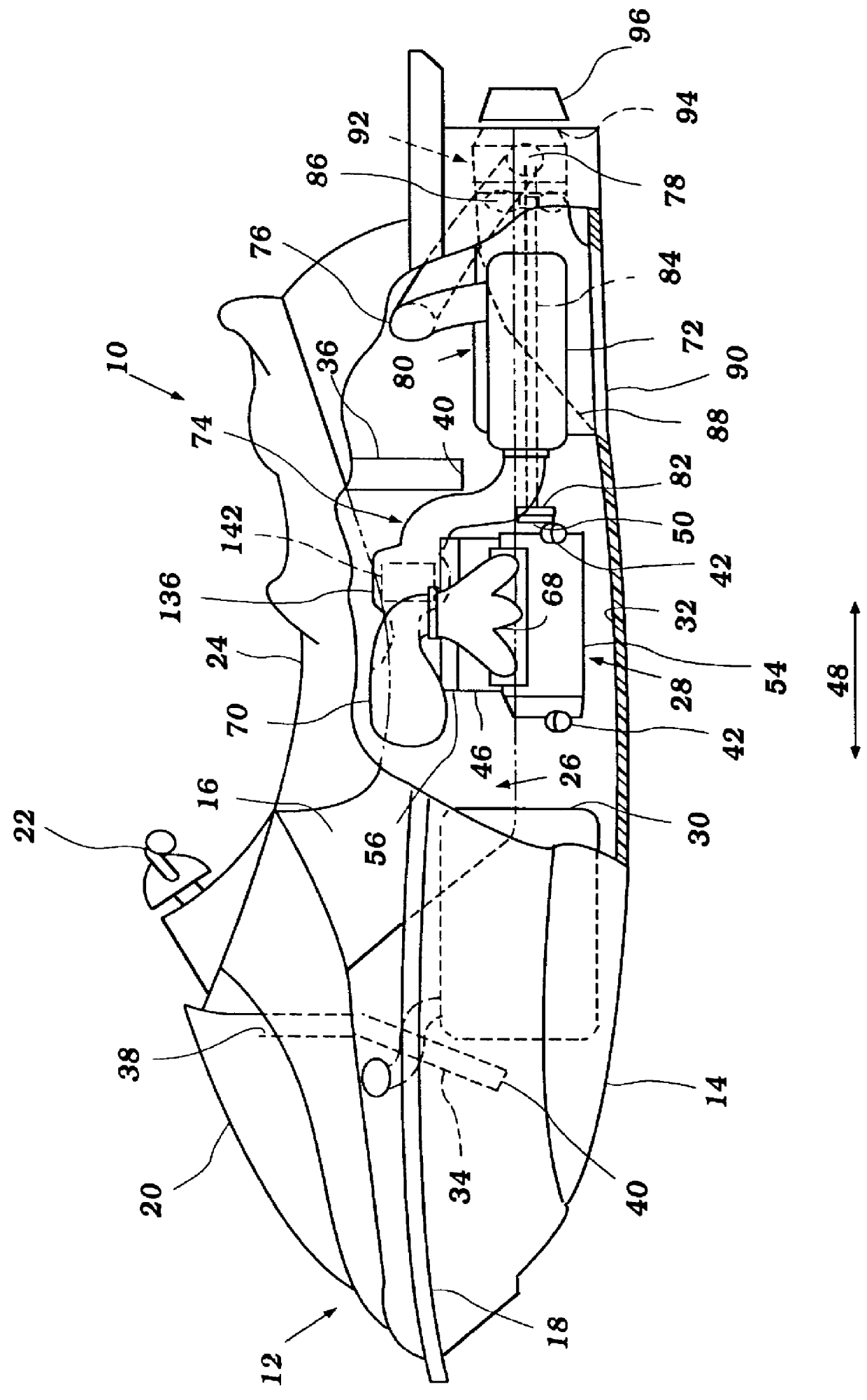
The present engine exhaust system has particular utility for use with a personal watercraft, and thus, the following describes the engine exhaust system in the context of a personal watercraft. This environment of use, however, is merely exemplary. The present engine exhaust system can be readily adapted by those skilled in the art for use with other types of watercraft as well, such as, for example, but without limitation, small jet boats and the like, as well as for use in other applications.

Before describing the present invention, an exemplary personal watercraft 10 will first be described in general detail to assist the reader's understanding of the engine and the inventive exhaust system described herein. The watercraft 10 is suited for movement through a body of water toward a front end or bow of the watercraft 10.

As illustrated in FIG. 1, the watercraft 10 includes a hull 12 formed by a lower section 14 and an upper deck section 16. The hull sections 14, 16 are formed from a ...


PUM


Abstract

An improved exhaust system for a marine engine utilizes a catalyst positioned within the exhaust system to maximize engine performance while minimizing the deterioration of catalyst. The exhaust system includes an exhaust manifold, an expansion chamber, a water trap and an exhaust pipe connecting the expansion chamber to the water trap. The exhaust pipe includes a catalyst chamber that houses the catalyst in such a way as to minimize the collection of water in the catalyst chamber as well as to inhibit a back flow of water to the catalyst chamber. The expansion chamber and the exhaust pipe are preferably fixed to the body of the engine to reduce vibration generated by the passage of the exhaust gases through the exhaust system.

Description

1. Field of the InventionThe present invention relates in general to an engine, and more particularly to an exhaust system for a marine engine.2. Description of Related ArtPersonal watercraft have become popular in recent years. This type of watercraft is sporty in nature; it turns swiftly, is easily maneuverable, and accelerates quickly. Personal watercraft today commonly carry one driver and one or two passengers and include a hull which defines an interior engine compartment for housing an engine. The output shaft of the engine is coupled to a water propulsion device of the watercraft, such as a jet propulsion unit. An internal combustion engine is commonly used to power the personal watercraft. Typically, the engine is an in-line, multi-cylinder, two-cycle engine.An exhaust system communicates with the cylinders of the engine and extends to a discharge that is located near the stem of the watercraft. In this manner, exhaust gases are expelled from the watercraft. To improve engi...

Claims


Application Information

Patent Timeline
Patent Type & Authority Patents(United States)
IPC IPC(8): B63B35/73F01N3/04F01N3/28F01N7/00F01N7/18F01N7/12B63H21/32F01N13/12F01N13/18
CPCB63B35/731F01N3/043F01N3/28F01N13/12F01N13/1805F01N2590/02Y02T10/20B63B34/10Y02T10/12
Inventor MASHIKO, TETSUYA
Owner YAMAHA MOTOR CO LTD
Why Eureka
Try Eureka