Face seal having strain induced face geometry

a face seal and geometry technology, applied in the direction of engine components, mechanical equipment, cutting machines, etc., can solve the problems of prolonging the life of the seal, affecting the sealing effect,

Inactive Publication Date: 2000-08-29
REEDHYCALOG LP
View PDF15 Cites 32 Cited by
  • Summary
  • Abstract
  • Description
  • Claims
  • Application Information

AI Technical Summary

Problems solved by technology

This lubricant film helps minimize the asperity contact of the two sealing surfaces and therefore prolongs seal life.
If the film becomes too thick, the ability to seal a pressure differential will be compromised.
If the film becomes too thin, frictional contact between the sealing faces will cause failure due to excessive face wear and/or overheating.
Although these hydrodynamic type packing ring elastomer seals have enjoyed commercial success in rock drilling bits, the seals are subject to thermal, chemical, and mechanical degradation when used in very severe drilling environments.
Also, because the seal is designed to pump lubricant out of the bit, there is a danger that the supply of lubricant will be depleted before the bearing wears out.
While these geometric modifications may serve to enhance seal lubrication, they can be difficult and costly to manufacture.
Because the seal's hydrodynamic behavior is very sensitive to...

Method used


Image

  • Face seal having strain induced face geometry
  • Face seal having strain induced face geometry
  • Face seal having strain induced face geometry

Examples


Embodiment Construction

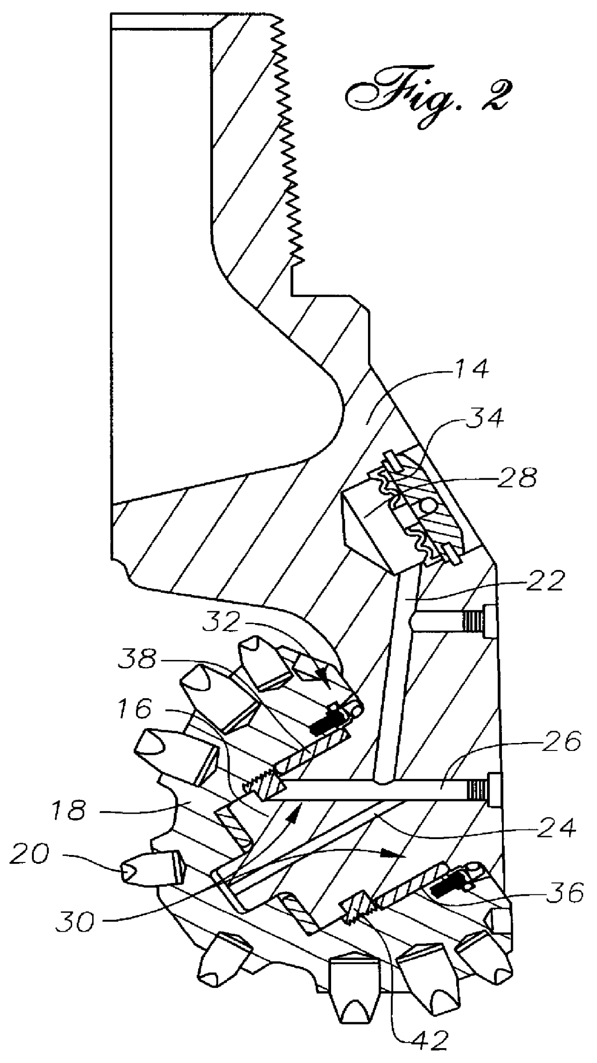
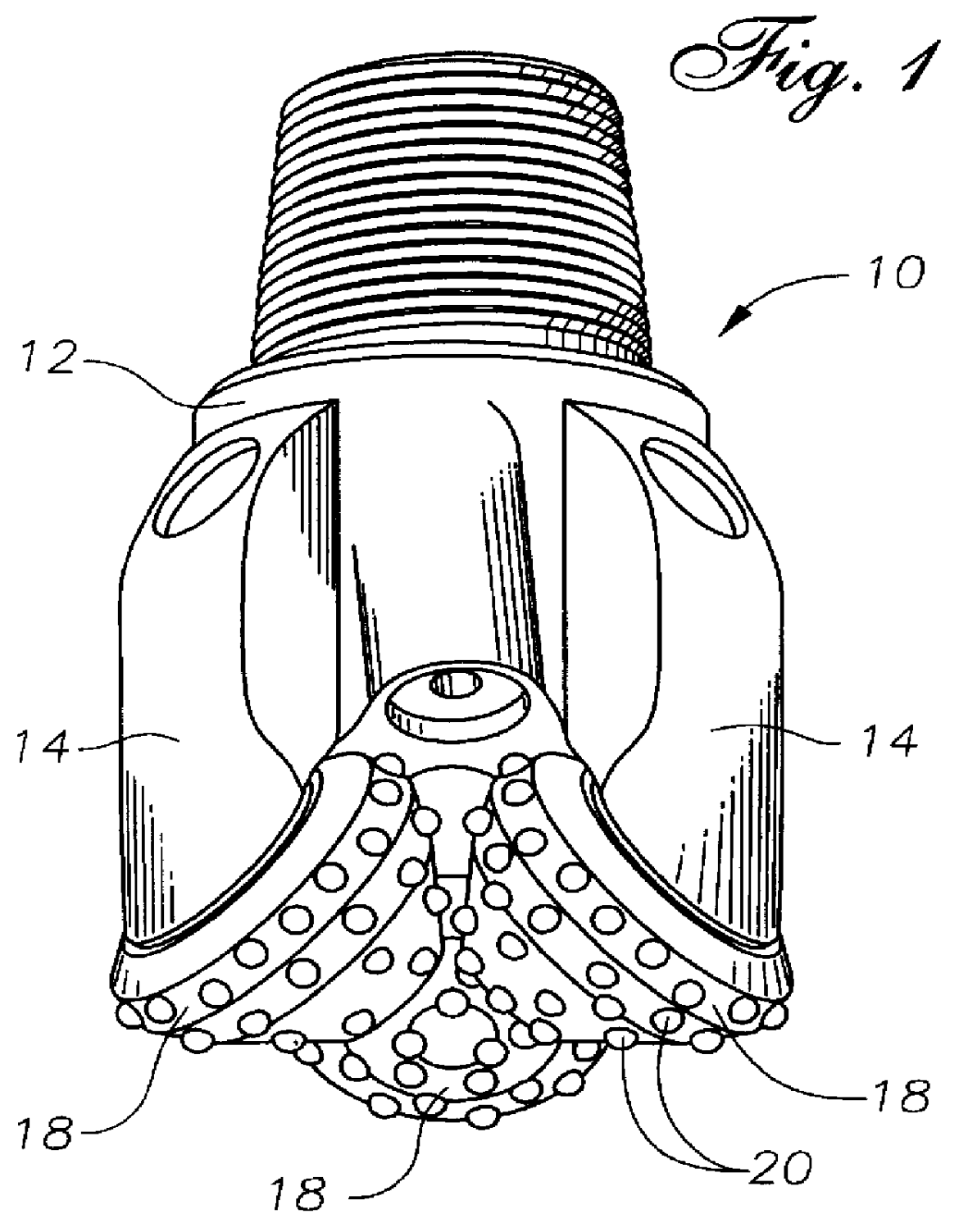
Referring now to the drawings in more detail, and particularly to FIGS. 1 and 2. A rolling cutter rock boring bit 10 includes a body 12 with a plurality of leg portions 14 attached to the body. A cantilevered bearing shaft 16 formed on each leg 14 extends inwardly and downwardly. A rolling cutter 18 is rotatably mounted upon the shaft 16. Attached to the rolling cutter 18 are hard, wear resistant cutting inserts 20 which engage the earth to effect a drilling action and cause rotation of the rolling cutter 18. A friction bearing member 36 is mounted between the bearing shaft 16 and a mating bearing cavity 38 formed in the cutter 18. This friction bearing 36 is designed to carry the radial loads imposed upon the cutter 18 during drilling. A retention bearing member 42 is mounted in the cutter 18 to retain the cutter 18 upon the bearing shaft 16 during drilling.

Internal passageways 22, 24, & 26, as well as a reservoir 28 and bearing area 30 of the leg 14, are filled with lubricant (not...


PUM


Abstract

A mechanical seal for rotary rock bits with a uniquely formed hydrodynamic wave geometry on the sealing faces. The sealing faces are first manufactured flat and smooth, then upon assembly are elastically deformed into a hydrodynamic geometry by an energizing system. After a smooth flat sealing surface is formed, the mechanical seal face elastically deforms into a hydrodynamic wave geometry. The typical deformation has a magnitude greater than about three helium light bands more than the original surface. The region of the sealing surface at the outer periphery of the seal does not have a wave geometry. Rather the portion of the seal face at the periphery is flat and parallel to its mating seal ring to exclude abrasives and eliminate lubricant leakage.

Description

1. Field of the InventionThis invention provides an enhanced rotary face seal design for roller cone rock bits. The new seal is elastically deformed at assembly to form a hydrodynamic wave geometry on the sealing interface. This wave geometry extends the seal life by enhancing the lubrication of the seal face.2. Description of the Related ArtRotary mechanical face seals are generally made up of two flat sealing faces which are designed to maintain a thin film of lubricant between the sealing faces. This lubricant film helps minimize the asperity contact of the two sealing surfaces and therefore prolongs seal life. Maintaining this lubricant film is particularly important in face seals for rotary drilling bits due to the unusually severe operating environment. As the sealing surfaces rotate relative to each other, they are urged together at a carefully controlled force by one or more energizers as shown, for instance, in U.S. Pat. Nos. 5,040,624; 4,838,365, and 3,761,145. It is of pa...

Claims


Application Information

Patent Timeline
IPC IPC(8): E21B10/08E21B10/22F16J15/34E21B10/25
CPCE21B10/25F16J15/3428
Inventor PEARCE, DAVID E.
Owner REEDHYCALOG LP
Why Eureka
Try Eureka