Windback device

a windback device and windback technology, applied in the direction of engine seals, climate sustainability, sustainable transportation, etc., can solve the problems of affecting the performance of gas turbines, affecting the sealing surface, and altering the oil, so as to reduce the build-up of fluid

Active Publication Date: 2009-12-31
STEIN SEAL
View PDF18 Cites 13 Cited by
  • Summary
  • Abstract
  • Description
  • Claims
  • Application Information

AI Technical Summary

Benefits of technology

[0016]This invention provides a windback and method of use as part of a seal assembly, which preferably may be implemented to eliminate lubricant leakage from a lubricant sump. Specifically, the windback preferably utilizes multiple inclined threads, each with an individual leak off slot, to improve windage pumping efficiency of the windback.
[0019]The windback is positioned over the shaft such that the collar substantially surrounds the shaft, affording the windback optimal radial clearance as respecting the distance between the ridges and the shaft. Specifically, the radial clearance is such that the inclined threads receive lubricant deposited thereon by windage resulting from rotation of the shaft. The radial clearance allows shear forces generated by rotation of the shaft to move the lubricant along the threads and through the leak-off slots of each thread.
[0021]In summary, in one of its aspects this invention provides a windback utilizing multiple inclined threads, improving windage pumping efficiency. This prevents or at least reduces lubricant migration from a lubricant sump to the sealing face of a sealing ring.
[0022]In another of its aspects the invention provides a windback utilizing multiple inclined threads to prevent lubricant from leaking from the lubricant sump.
[0023]In another of its aspects the invention prevents lubricant leakage from a low pressure area, e.g. a lubricant sump, to a high pressure area, e.g. the gas side of a turbine engine.
[0024]In another of its aspects the invention redirects lubricant flow along a shaft back into a lubricant sump while reducing lubricant build-up within the windback.

Problems solved by technology

For example, when an oil lubricant is used, mixing the oil with the gas could result in formation of oil coke, which is a byproduct of oil heated to an elevated temperature and which chemically alters the oil and hence is detrimental to the gas turbine.
Oil coke can foul seal surfaces and prevent proper bearing lubrication.
These pressure differentials, along with shaft windage, tend to move the lubricant out of the sump and along the shaft, a phenomenon often termed “lubricant splash,” which results in loss of lubricant from the lubricant sump.
However, the shaft seal, which typically is a segmented carbon rubbing seal, may have the carbon sealing faces contaminated by the lubricant if the lubricant reaches the seal.
Such contamination of the seal can compromise the integrity of the seal and reduce the efficiency with which the seal isolates the lubricant within the lubricant sump.
However experiments have shown that, even in such applications, the pressure in the sump adjacent the seal was lower than the pressure in the remainder of the sump, thus causing additional lubricant flow along the shaft towards the seal.
Because of this unexpected pressure profile, windback devices prior to the aforementioned research failed to fully prevent the flow of lubricant toward the seal.
When the shaft rotates, windage results in the clearance between the windback and the shaft.
The additional distance and single leak off slot also increases the risk that the windback will clog or be backed up with lubricant, reducing efficiency of the helical thread (A).
To this end, in '298 fluid can build within the grooves, leading to a decrease in the windage pumping efficiency and reintroduction of lubricant into the space between the shaft and the windage.

Method used


Image

  • Windback device
  • Windback device
  • Windback device

Examples


example 1

Dimensions of Windbacks Tested

[0060]Nine different windback designs of various pitch angles and numbers of inclined threads were tested against standard designs for evaluating the improved efficiency and effective flow rates of the inclined threads. These designs include a 0.06 inch pitch windback design (No. 14167-12), a 6 inclined thread windback design (No. 14167-02), a tapered bore windback design (No. 14167-13), a standard windback design (No. 14167-01), a 3 inclined thread windback design (No. 14167-07), (0.125 inch) pitch windback design (No. 14167-11), a 4 inclined thread windback design (No. 14167-10), a 6 inclined thread windback design (No. 14167-09), a 24 inclined thread windback design (No. 14167-14), and a 12 inclined thread windback design (No. 14167-08). These improved thread designs, and the standard design, were machined into windbacks in accordance with the present invention. The specific dimensions of each windback, including thread diameter, radial clearance, ax...

example 2

Testing Procedures

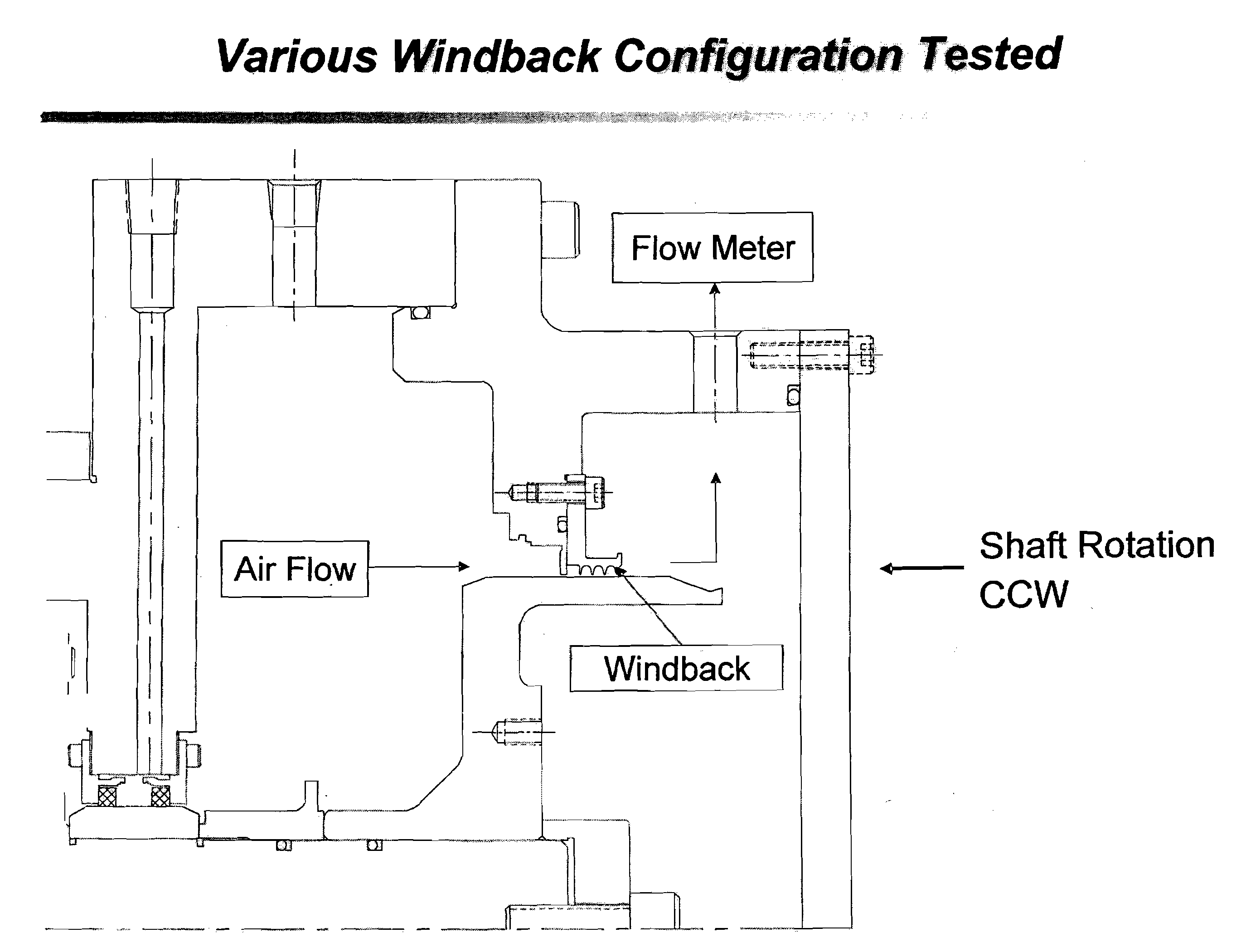
[0061]Prior to testing the foregoing 10 windback test designs a dry dynamic test was performed without a windback to establish the baseline flow rates associated with the shaft rotation. More specifically, referring to FIG. 11, a test chamber was prepared without a windback and the air flow, indicated by the arrows of FIG. 11, generated from the rotation of the shaft was measure by a flow meter. The shaft was rotated in an environment with no PSID, as measured by a water manometer, with a set slave seal buffer at 10 psig. The seal chamber was vented to the atmosphere and no oil was fed through the runner. The shaft was then rotated at 2,000 rpm and baseline air flow measurements were taken at 5 minute intervals for 20 minutes. The shaft was then rotated at 4,000 rpm and baseline air flow measurements were taken at 5 minute intervals for 20 minutes. The shaft was then rotated at 6,000 rpm and baseline air flow measurements were taken at 5 minute intervals for 20 min...

example 3

Results of Testing Procedures

[0064]As illustrated in FIG. 13, the results of the foregoing testing procedures indicate that windback designs with 12, 24, 6, 4, and 3 inclined threads all had a greater flow efficiency than the standard windback design. Additionally, the windback with the 0.125 pitch angle also provided greater flow efficiency. Accordingly, the results of the testing procedure confirmed that the threads of the present windback design alter the air flow rate generated by the rotation of the runner with greater efficiency that those designs known in the art. Accordingly, the present windback device redirect fluid entering the space between a windback and the shaft back into the sump with greater efficiency that the standard windback designs.


PUM


Abstract

The present invention relates to a windback device and method of use to prevent lubricant from leaking from a lubricant sump. More specifically, the present invention is comprised of a windback device within a lubricant sump formed from the coupling of an annular sump housing, an annular fluid seal assembly, and a bearing. The annular housing substantially surrounds the runner to form a chamber. The seal assembly is coupled to a sump housing both of which are adapted to receive a rotatable runner such that a sealed chamber is formed around the runner. A plurality of inclined threads extend along an inner face of the windback device and are angled such that lubricant or fluid splashed from the rotating shaft is redirected away from a shaft seal element of the annular fluid seal and through leak off slots leading to the sump housing chamber.

Description

BACKGROUND OF THE INVENTION[0001]1. Field of the Invention[0002]This invention is directed to a windback device with a rotating shaft and positioned between a lubricant sump and a shaft seal so as to prevent lubrication fluid from reaching the seal.[0003]2. Description of the Prior Art[0004]With rotating shafts, lubricant sumps are frequently required along segments of the shaft to provide lubrication for shaft bearings and the like. It is frequently desirable to isolate the lubricant sump from remaining media in which the shaft is immersed, as well as to assure that the lubricant remains in the sump so that (1) lubrication of the bearings may continue and (2) the lubricant does not contaminate any other media in which the shaft is immersed.[0005]For example, in gas turbine applications the lubricant sump is typically isolated from the remainder of the gas turbine housing by the sump housing and a shaft seal. The remainder of the gas turbine housing, or a compartment adjacent theret...

Claims


Application Information

Patent Timeline
Patent Type & Authority Applications(United States)
IPC IPC(8): F01D11/02
CPCY02T50/671F01D11/02Y02T50/60
Inventor ROCHE, BRIANGARRISON, GLENNPATEL, HIRENEPPEHIMER, JOHNVASAGAR, MANIKSANVILLE, MARKPILLAI, SAJI
Owner STEIN SEAL
Why Eureka
Try Eureka