Compressor pump coupling method

A technology of compressor pump and compressor shell, applied in the direction of pump, pump components, mechanical equipment, etc., can solve the problems of reducing the air tightness of compressor shell, affecting the air tightness of welding holes, and leakage of lubricating oil, etc. Eliminate the leakage of lubricating oil, high assembly and processing efficiency, and increase the effect of air tightness

Inactive Publication Date: 2007-04-25
LG ELECTRONICS (TIANJIN) APPLIANCES CO LTD
View PDF0 Cites 3 Cited by
  • Summary
  • Abstract
  • Description
  • Claims
  • Application Information

AI Technical Summary

Problems solved by technology

[0009] However, there is a problem of poor airtightness of the welding holes in the above-mentioned prior art compressor pump body connection method utilizing the three-point welding method.
Due to the thermal stress caused by uneven welding heating and the existence of welding slag, the airtightness of the weldin

Method used


Image

  • Compressor pump coupling method
  • Compressor pump coupling method

Examples


Example Embodiment

[0027] The specific embodiments of the present invention will now be further described with reference to the accompanying drawings.

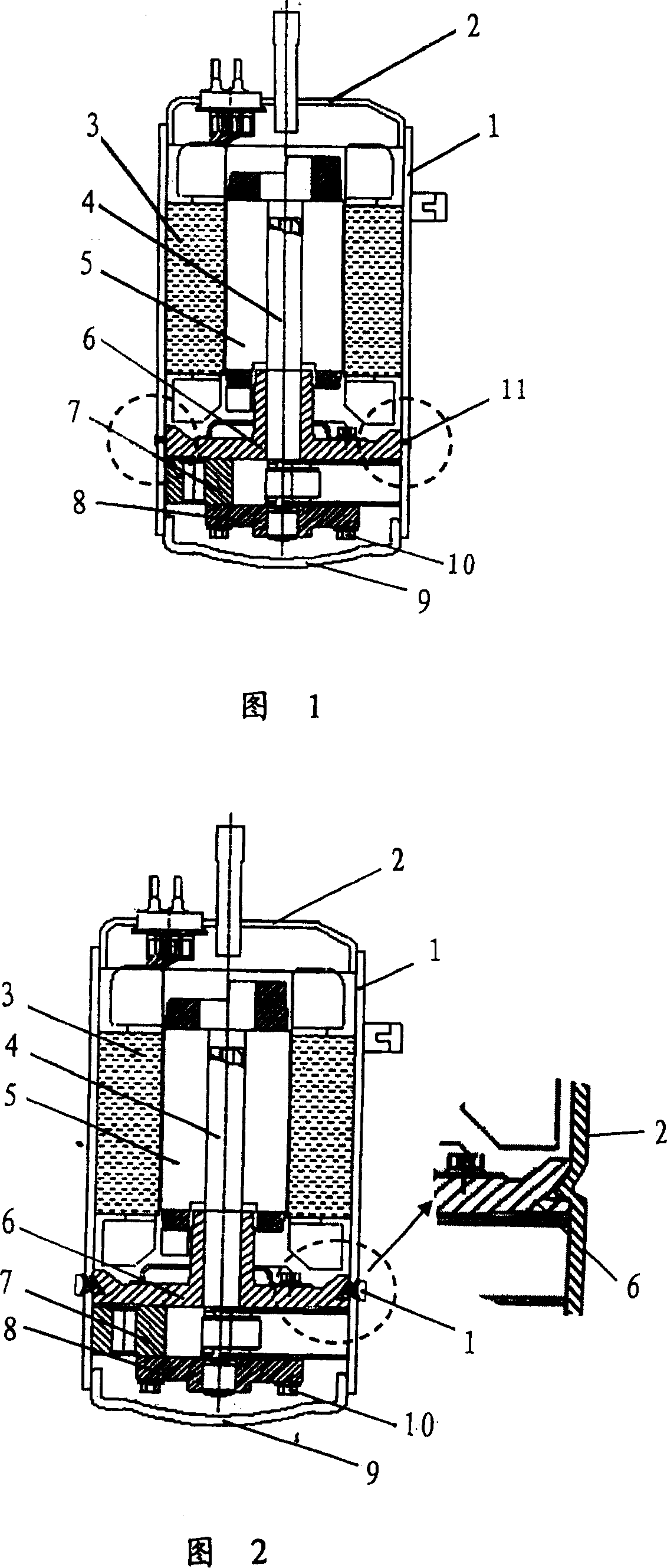
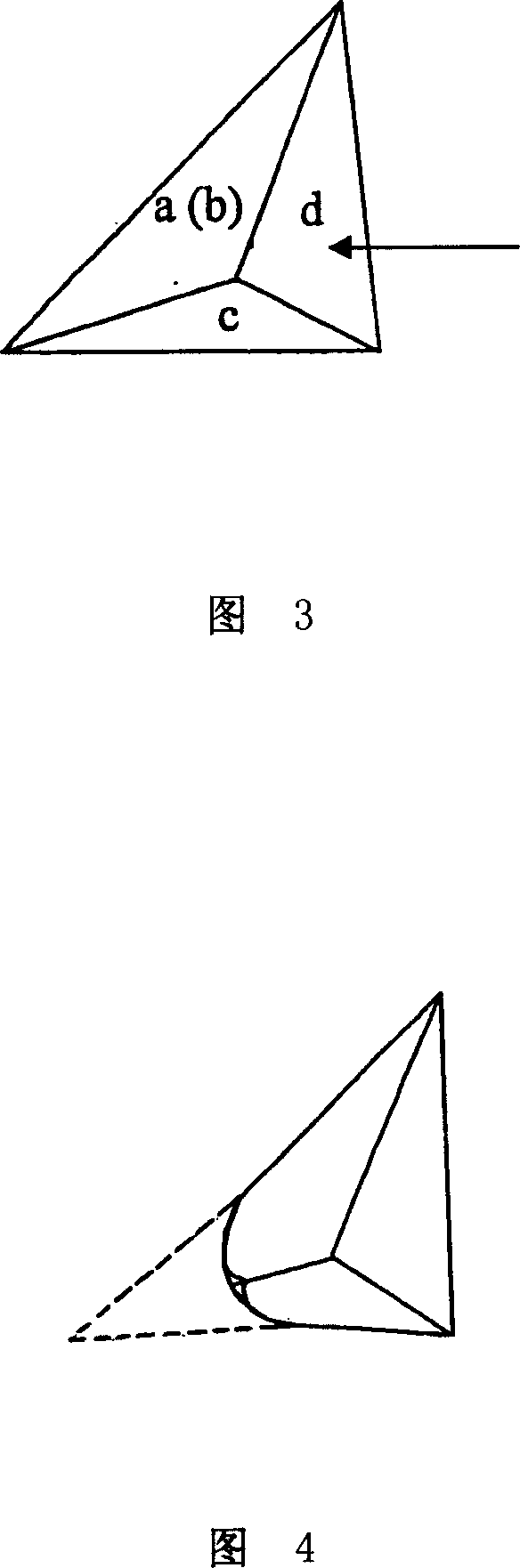
[0028] Fig. 2 shows the structure of the compressor connecting the pump body and the casing using the present invention, Fig. 3 shows the groove shape of the compressor main bearing in the present invention, and Fig. 4 shows the punch shape of the present invention for punching the casing.

[0029] The coupling method of the compressor pump body involved in the present invention includes two steps of slotting the main bearing and punching the casing.

[0030] Main bearing slotting: Before the compressor is assembled, four stamping grooves with the shape shown in Figure 3 are machined on the annular end face of the main bearing 6 that is in contact with the shell 1. The four stamping grooves are in an orthogonal position. The inner cavity is in the shape of a tetrahedron. The four triangular faces of the tetrahedron are respectively a, b, c, and...


PUM


Abstract

The invention relates to a stamping shell method, by which compressor pump and shell is fixed connection, comprising opening groove on the main bearing and stamping shell. Opening groove on the main bearing is that before compressor assembling, four stamping grooves are machined on the circular face where main bearing is contacted with shell and their cavity is tetrahedral shape, one triangle face of the tetrahedral body is parallel with end face of the main bearing; stamping shell is that when compressor is assembled, shell is stamped from outer to inner by plunger at the position on the stamping groove of the main bearing relative to the shell outside so that stamping part of shell depresses into the stamping groove of main bearing. The invention makes compressor pump and shell without welding hole is fixed connection and increases air-tightness of compressor shell. The oil leakage of compressor is avoided.

Description

technical field [0001] The invention relates to a method for assembling a compressor, in particular to a method for connecting a pump body and a casing of the compressor. Background technique [0002] Compressors are important components of household appliances such as air conditioners and refrigerators that use the refrigeration cycle system to work. Generally speaking, the compressor uses its moving parts (rolling piston or reciprocating piston, etc.) driven by the motor to convert mechanical energy into pressure energy, realize the compression of the refrigerant in the cylinder of the compressor pump body, and compress the compressed refrigerant The discharged compressor enters the refrigeration cycle system for circulation. [0003] Commonly used compressors mainly include reciprocating piston compressors and rotary compressors. The rolling piston compressor is the most common rotary compressor. It has the characteristics of small size, simple structure, stable operati...

Claims


Application Information

Patent Timeline
IPC IPC(8): F04C29/00F04C18/00
Inventor 张金兰
Owner LG ELECTRONICS (TIANJIN) APPLIANCES CO LTD
Why Eureka
Try Eureka