Method and apparatus for slurry polishing

a technology of slurry and slurry, which is applied in the direction of polishing compositions, chemistry apparatus and processes, polishing compositions with abrasives, etc., can solve the problems of large portion of slurry used during the cmp processions failing to reach the wafer, circuits being either non-functional or, at best, endowed with less than optimal performance, etc., and achieves high viscosity

Inactive Publication Date: 2000-08-29
GLOBALFOUNDRIES INC
View PDF7 Cites 155 Cited by
  • Summary
  • Abstract
  • Description
  • Claims
  • Application Information

AI Technical Summary

Benefits of technology

The present invention is a method and apparatus for conducting Chemical-Mechanical P

Problems solved by technology

If the wafer surface was sufficiently non-planar, the resulting structures would be poorly defined, with the circuit being either non-functional or, at best, endowed with less than optimum performance.
There are a number of disadvantages associated with the conventional CMP process.
In current CMP processes, there is no mechanism for addressing th

Method used


Image

  • Method and apparatus for slurry polishing
  • Method and apparatus for slurry polishing
  • Method and apparatus for slurry polishing

Examples


Embodiment Construction

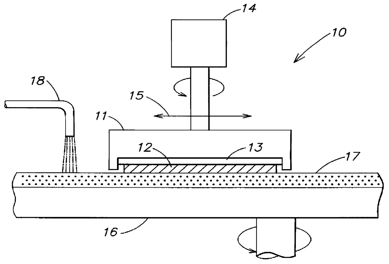
The present invention teaches a novel and useful method and apparatus for making and using a high viscosity slurry for CMP processing as explained in connection with FIG. 3.

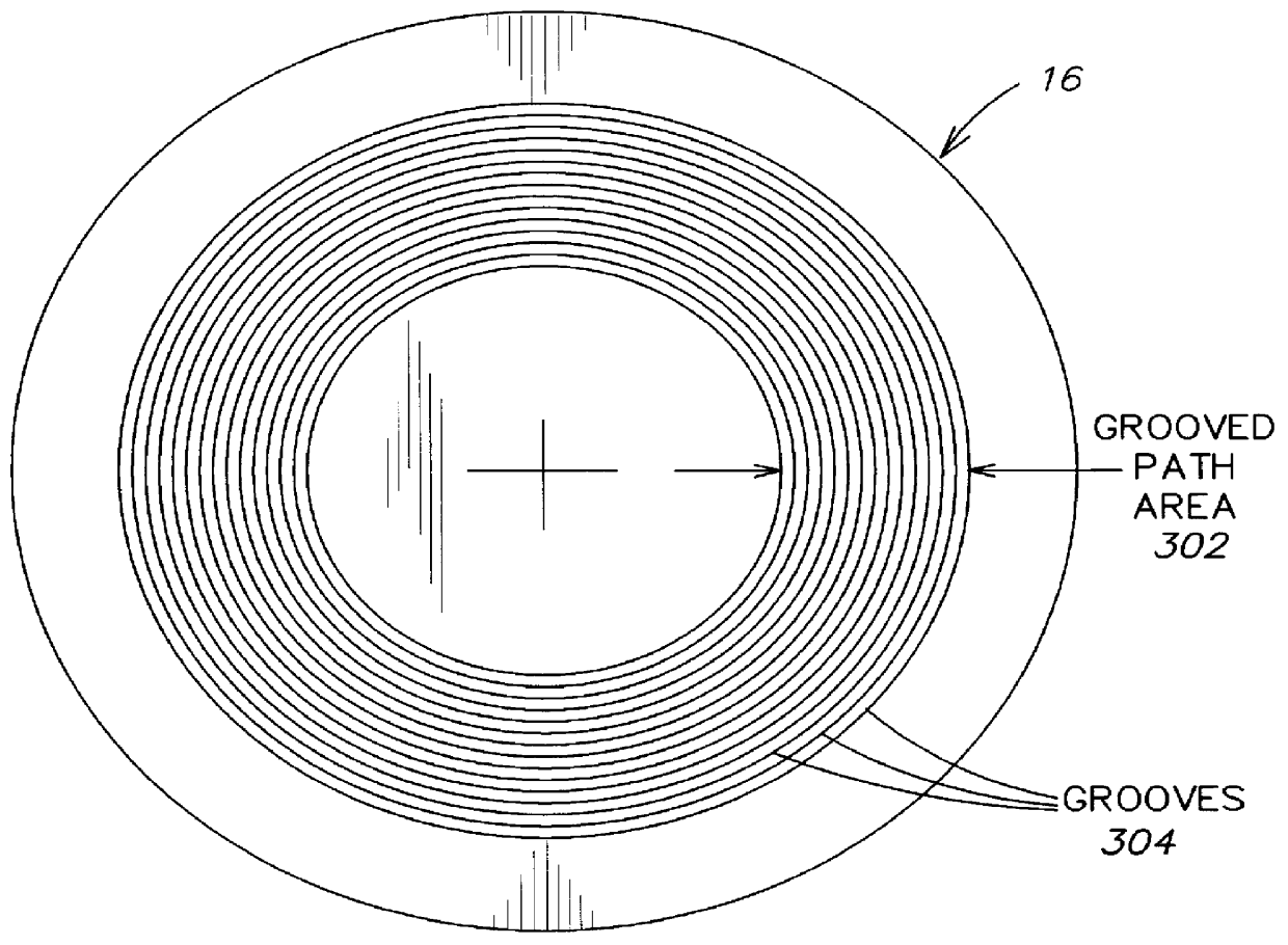
Reference now being made to FIG. 3, a diagram is shown illustrating in greater detail the polishing pad 16 as modified according to the teachings of the preferred embodiment of the present invention. As illustrated, the polishing pad 12 has been modified to include a series of substantially circumferential grooves 304 formed across the portion of the pad 16 over which polishing takes place. The macro grooves 304 aid in polishing by channeling slurry between the substrate surface and the pad 16. The macro grooves 304 are formed prior to polishing by means of a milling machine a lathe, a press or other similar method. Since polishing does not normally occur across the entire pad surface, the grooves 304 are usually only formed into a portion of the pad over which polishing takes place as indicated by the grooved pa...


PUM

PropertyMeasurementUnit
Temperatureaaaaaaaaaa
Fractionaaaaaaaaaa
Viscosityaaaaaaaaaa

Abstract

A method and apparatus for Chemical-Mechanical Polishing of semiconductor wafers using various formulations of high viscosity slurry.

Description

1. Technical Field of the Present InventionThe present invention generally relates to a polishing apparatus and a method for performing a polishing operation. More specifically, the present invention is an improved method and apparatus for performing polishing using a high viscosity slurry.2. Background of the Present InventionIn the manufacture of integrated circuits, wafer surface planarity is of extreme importance. Photolithographic processes are typically pushed close to the limit of resolution in order to create maximum circuit density. For a 16 mb dynamic random access memory, minimum critical dimensions, such as wordline and bitline width will initially be in the 0.5.mu.-0.7.mu. range. Since these geometries are photolithographically produced, it is essential that the wafer surface be highly planar so that the electromagnetic radiation used to create a masking layer may be accurately focused at a single level thus resulting in precise imaging over the entire surface of the wa...

Claims


Application Information

Patent Timeline
IPC IPC(8): C09G1/00C09G1/02H01L21/302
CPCB24B37/26C09G1/02H01L21/302
Inventor MORGAN, III, CLIFFORD O.RUTTEN, MATTHEW J.WALTON, ERICK G.WRIGHT, TERRANCE M.
Owner GLOBALFOUNDRIES INC
Why Eureka
Try Eureka