Filter tuning device and tuning plate including a number of such devices

Inactive Publication Date: 2000-08-29
TELEFON AB LM ERICSSON (PUBL)
View PDF13 Cites 22 Cited by
  • Summary
  • Abstract
  • Description
  • Claims
  • Application Information

AI Technical Summary

Benefits of technology

is to minimize the problem of the currents not taking the shortest route to earth by using straight slits instead of the curved slits used in the state of the art tuning plate. Yet another object of the invention is the use of spring-elements integrated in the tuning plate to ob

Problems solved by technology

It can be seen that the present approaches, present problems.
First, the tuning of the first type of state of the art filters that are tuned without using a tuning plate creates a problem when autotesting because of the need for two tools when tightening the locking nut.
This method is cumbe

Method used


Image

  • Filter tuning device and tuning plate including a number of such devices
  • Filter tuning device and tuning plate including a number of such devices
  • Filter tuning device and tuning plate including a number of such devices

Examples


Embodiment Construction

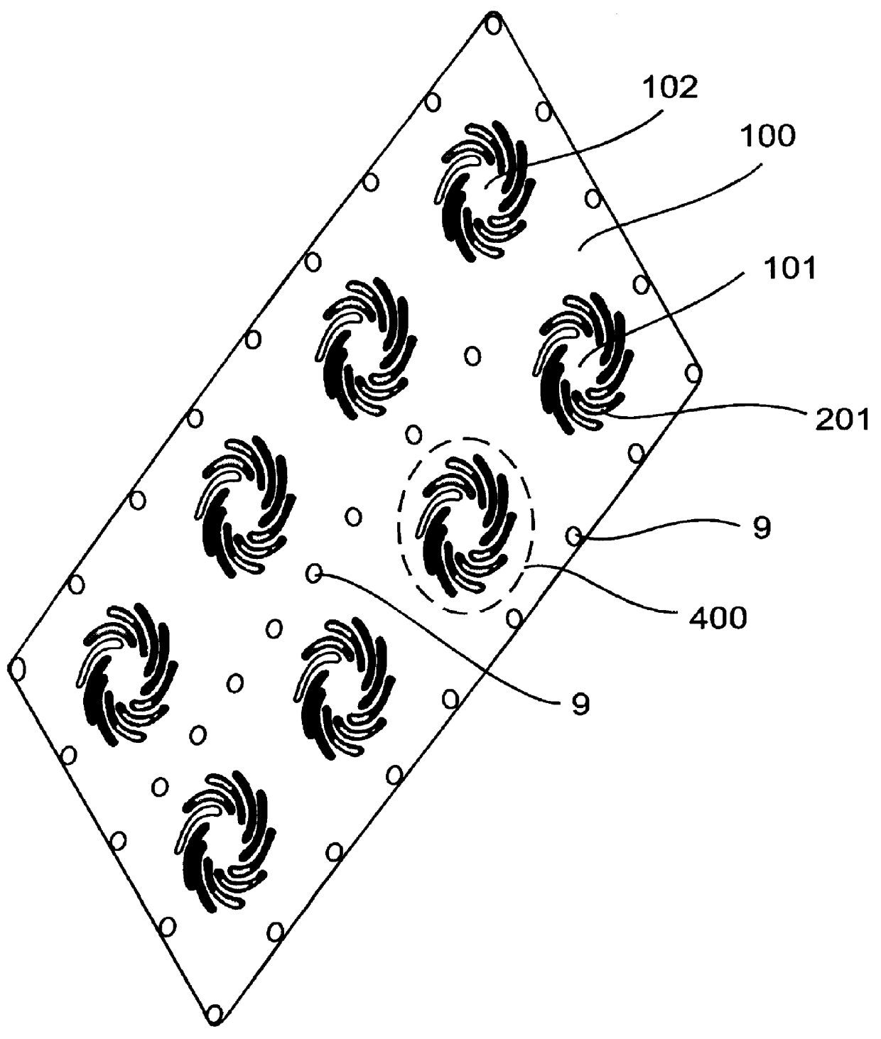
Briefly described, the present invention provides an apparatus for tuning of radio / BP-filters used in e.g. mobile radio systems. The present invention focuses on the tuning plate 300 placed between the body 111 and the lid 110.

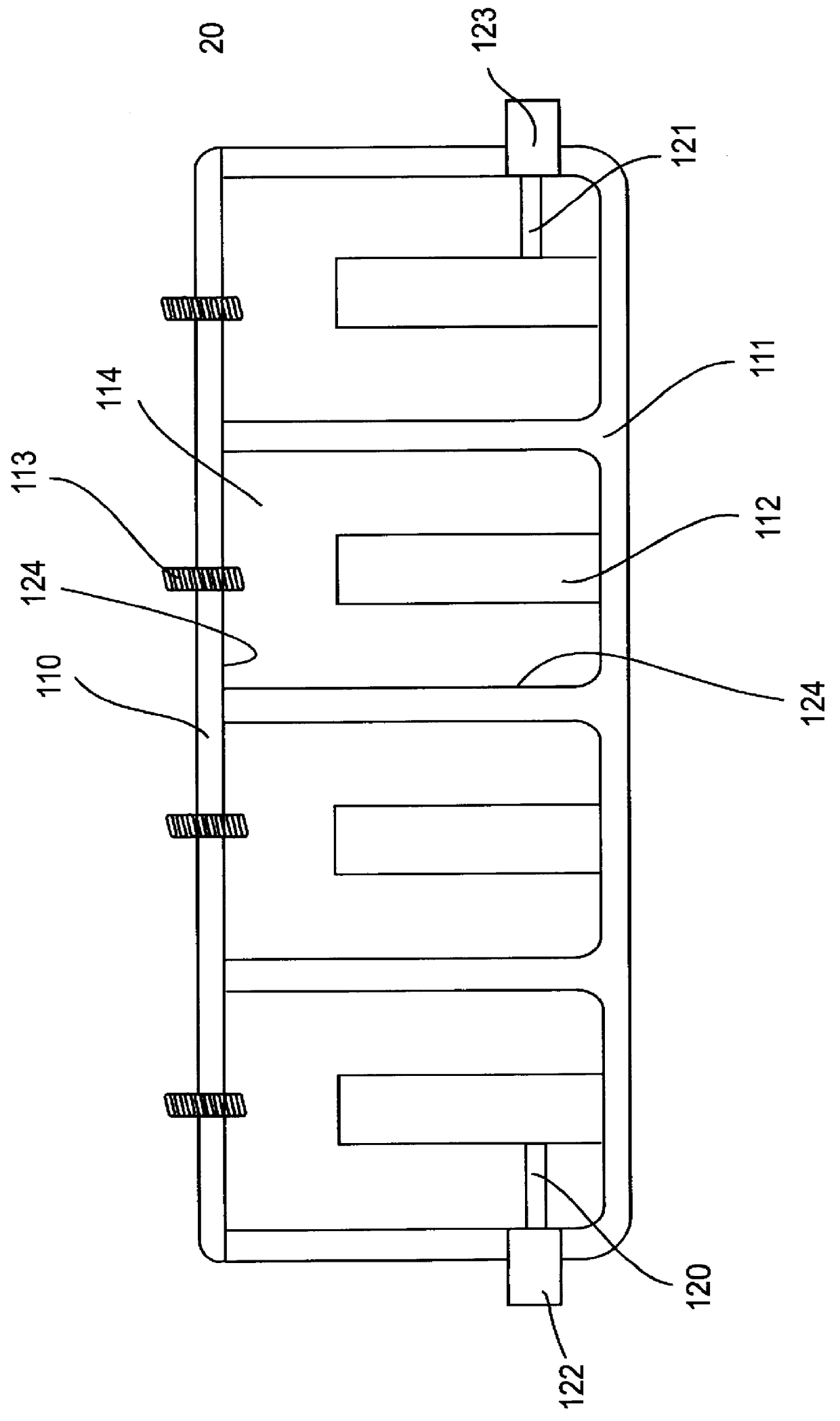
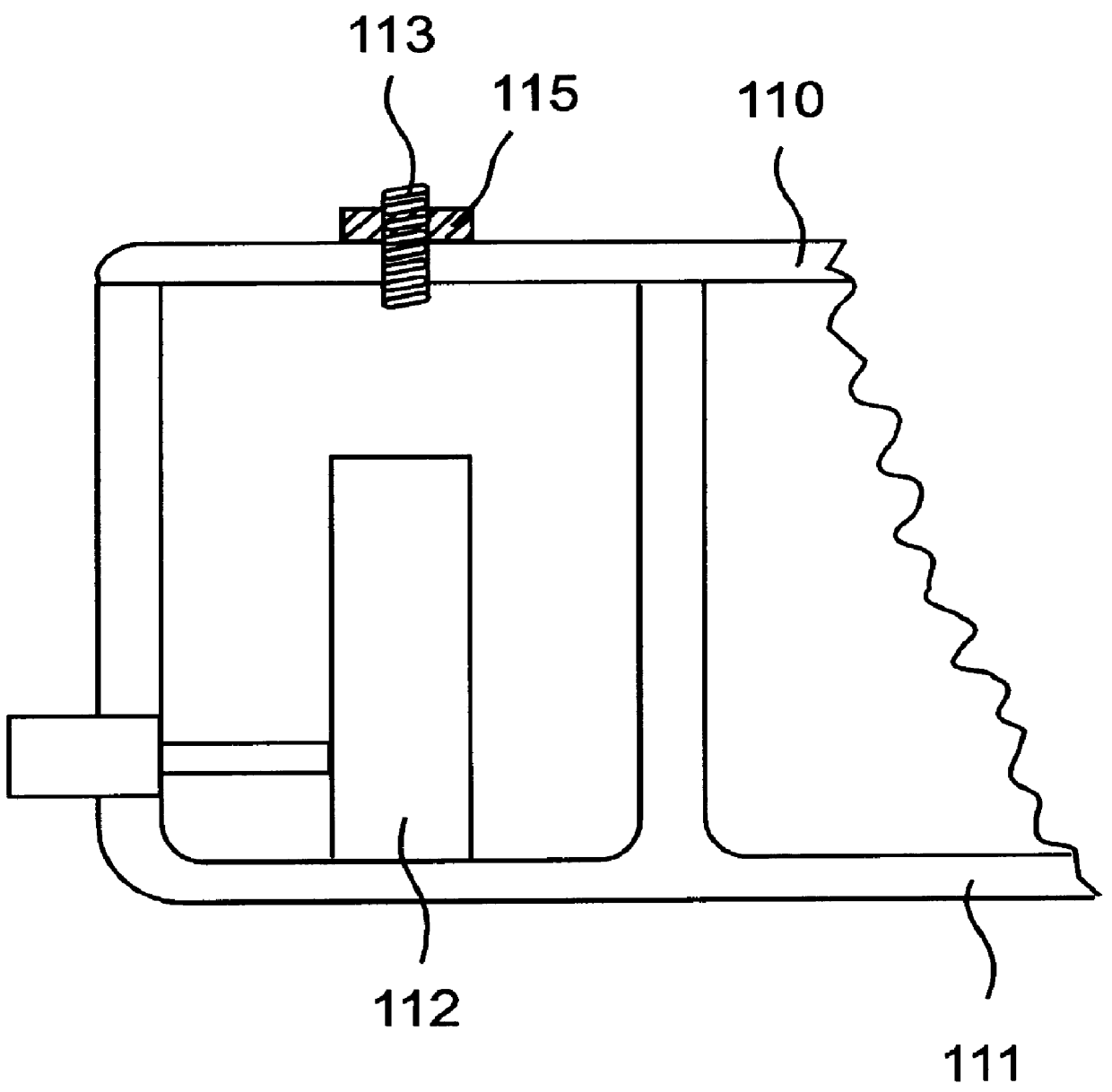
FIG. 1 schematically illustrates a side cutaway view of a state of the art filter 20 for e.g a mobile telephone system. A conventional BP(bandpass)-filter includes a body 111, a lid 110, filter cavities 114, center conductors 112, tuning screws 113, an input loop 120, an output loop 121 and connectors 122, 123. The walls 124 of the filter cavities 114 are formed by the inner surfaces of a filter casing. The filter casing is formed from the hollowed-outbody 111 and the lid 110. Center conductors 112 are placed inside the filter cavities 114. Tuning screws 113 for tuning the filter, that is the center conductors 112, to the right frequency are arranged in the lid 110 and extend into the filter cavities 114. One tuning screw 113 is arranged in the lid 110 for eve...


PUM


Abstract

The present invention relates to a tuning device in radio filter equipment for mobile telephony in which one or more cavities in the equipment should be tuned to the right frequency. The invention also relates to a tuning plate including a number of such tuning devices. The tuning device preferably includes regular or square formed depressed parts in the tuning plate. The depressed part converges each to a square formed central plate which is provided with an elevation or bulb. By turning a tuning screw on the equipment a force is developed on the plate and the surrounding depressed parts. This implies that the tuning can be made automatically, more secure and with less risk for intermodulation.

Description

The present invention relates generally to radio filters, e.g bandpass filters which may be in the HF-area, used in e.g. a mobile radio system, and more particularly to the tuning of such filters.DESCRIPTION OF RELATED ARTSome kind of tuning arrangement is needed to tune a HF-filter to the right frequency. This may for example be done with a tuning screw alone or with a tuning plate where a tuning screw moves a part of the tuning plate.A conventional BP(bandpass)-filter includes a body, a lid, filter cavities, center conductors, tuning screws, an input loop, an output loop and connectors. The walls of the filter cavities are formed by the inner surfaces of a filter casing. The filter casing is formed from the hollowed-out body and the lid. Center conductors are placed inside the filter cavities. Tuning screws for tuning the filter, that is the center conductors, to the right frequency are arranged in the lid and extend into the filter cavities. One tuning screw is arranged in the li...

Claims


Application Information

Patent Timeline
IPC IPC(8): H01P1/20H01P1/205H01P7/04
CPCH01P1/2053
Inventor HENNINGSSON, BO UNO EGONLINDELL, SVEN PATRIK
Owner TELEFON AB LM ERICSSON (PUBL)
Why Eureka
Try Eureka