Securing ring ("c" clip)

a fastening ring and c-clip technology, applied in the direction of fastening means, couplings, rod connections, etc., can solve problems such as affecting the ability of axial forces to be absorbed by the ring

Inactive Publication Date: 2000-09-05
HANS OETIKER MASCHEN & APPFAB
View PDF12 Cites 23 Cited by
  • Summary
  • Abstract
  • Description
  • Claims
  • Application Information

AI Technical Summary

Problems solved by technology

Disadvantageously, however, the U-shaped clip engages with the circumferential annular groove of the shaft only along limited regions, thereby impairing its capability to absorb axial forces.

Method used


Image

  • Securing ring ("c" clip)
  • Securing ring ("c" clip)

Examples


Embodiment Construction

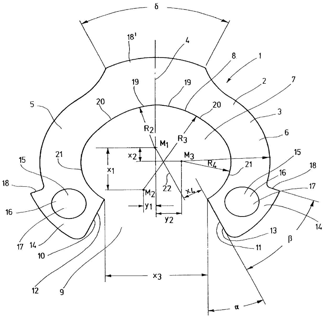
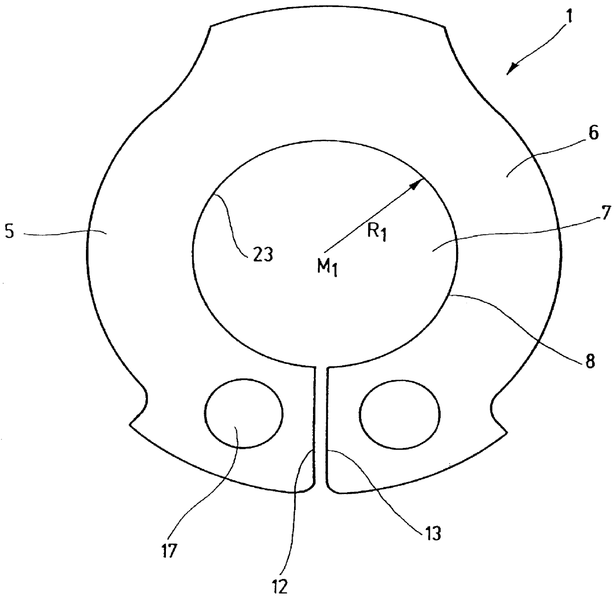
Referring now to FIG. 1, there is shown a slotted fastening ring 1 formed as a stamped sheet metal part 2. The ring is essentially made from a non-resilient cold-formable material 3.

With reference to an imaginary line of symmetry 4, the fastening ring 1 comprises two ring halves 5 and 6 which are made as a single piece and which are formed such as to represent mirror images of each other with respect to the line of symmetry 4. In the following, only one of the ring halves 5, 6 will be described in detail for sake of simplicity. The same reasoning then applies to the respective other ring half 5, 6. The fastening ring 1 has an inside opening 7 defining a contour 8. On one side, the contour 8 extends up to a slot 9 formed between the ring tips 10, 11. The marginal edges 12, 13 of the slot which correspond to the ring tips 10, 11, form an angle .alpha. with the line of symmetry 4. This angle .alpha. is 25.42.degree. for a fastening ring 1 with a radius R.sub.1 of 10 mm after installati...


PUM


Abstract

The invention relates to slotted fastening ring for making a formfitting connection by compressing or expanding, respectively, the slotted fastening ring during installation or removal, respectively. It is provided that the fastening ring (1) is made from an essentially non-resilient cold-formable material (3) and that the ring tips (10, 11) between which the slot (9) is formed, are spaced apart-when the fastening ring (1) is not installed-such as to be capable-for the purpose of installing the ring (1)-of being bent towards each other under plastic deformation, so that the fastening ring (1) attains a closed position, with the inside opening (7) of the ring taking on a circular or a substantially circular contour (8).

Description

1. Field of the InventionThe present invention relates to slotted fastening ring for making a formfitting connection by compressing or expanding, respectively, the slotted fastening ring during installation or removal, respectively.2. Description of the Related ArtFastening rings of the type described above are known in the art as Seeger rings or circlip rings. These rings are used to secure the axial position of components, for example, on a shaft or inside a bore. When the respective fastening ring is installed or removed, the ring is extended outwardly or inwardly, as the case may be, with the resilient forces urging the ring which is made from an elastic material, back to its original or ground state. The ground state is defined as the state wherein the fastening ring is not installed. The conventional fastening rings are formed as spiral springs, wherein the resilient properties in the axial direction are essentially inconsequential for attachment on a shaft. The known rings en...

Claims


Application Information

Patent Timeline
Patent Type & Authority Patents(United States)
IPC IPC(8): F16B21/16F16B21/00
CPCF16B21/16Y10T403/69Y10T403/53
Inventor ALLERT, KURT
Owner HANS OETIKER MASCHEN & APPFAB
Why Eureka
Try Eureka