Modular element for storage basin construction, supporting structure, method of construction thereof

a technology of modular elements and storage basins, applied in the field of modular elements, can solve the problems of high concrete consumption rate, difficulty in fabrication of modular elements, and additional manual work, and achieve the effect of reducing the consumption of hardening materials

Active Publication Date: 2015-09-17
BREAZ LAUREN&TCEDIL IU DUMITRU
View PDF3 Cites 3 Cited by
  • Summary
  • Abstract
  • Description
  • Claims
  • Application Information

AI Technical Summary

Benefits of technology

[0029]3. reduced consumption of hardening material for obtaining the supporting structure.

Problems solved by technology

The disadvantage of this technical solution consists in a high rate of concrete consumption, flow problems when casting the concrete, due to the form of the internal channels, positioned perpendicularly along the vertical and horizontal axes; also, a too complex construction and additional manual working, brought about by the network of bars.
The disadvantage of this solution is the difficulty of fabrication said modular elements.
The disadvantage of this technical solution is casting the concrete each time after one row of the dome like construction is built, implying high costs and supplementary time for the labour.
Moreover, it does not permit the distribution of concrete between the successive layers of construction elements.

Method used


Image

  • Modular element for storage basin construction, supporting structure, method of construction thereof
  • Modular element for storage basin construction, supporting structure, method of construction thereof
  • Modular element for storage basin construction, supporting structure, method of construction thereof

Examples


embodiment 1

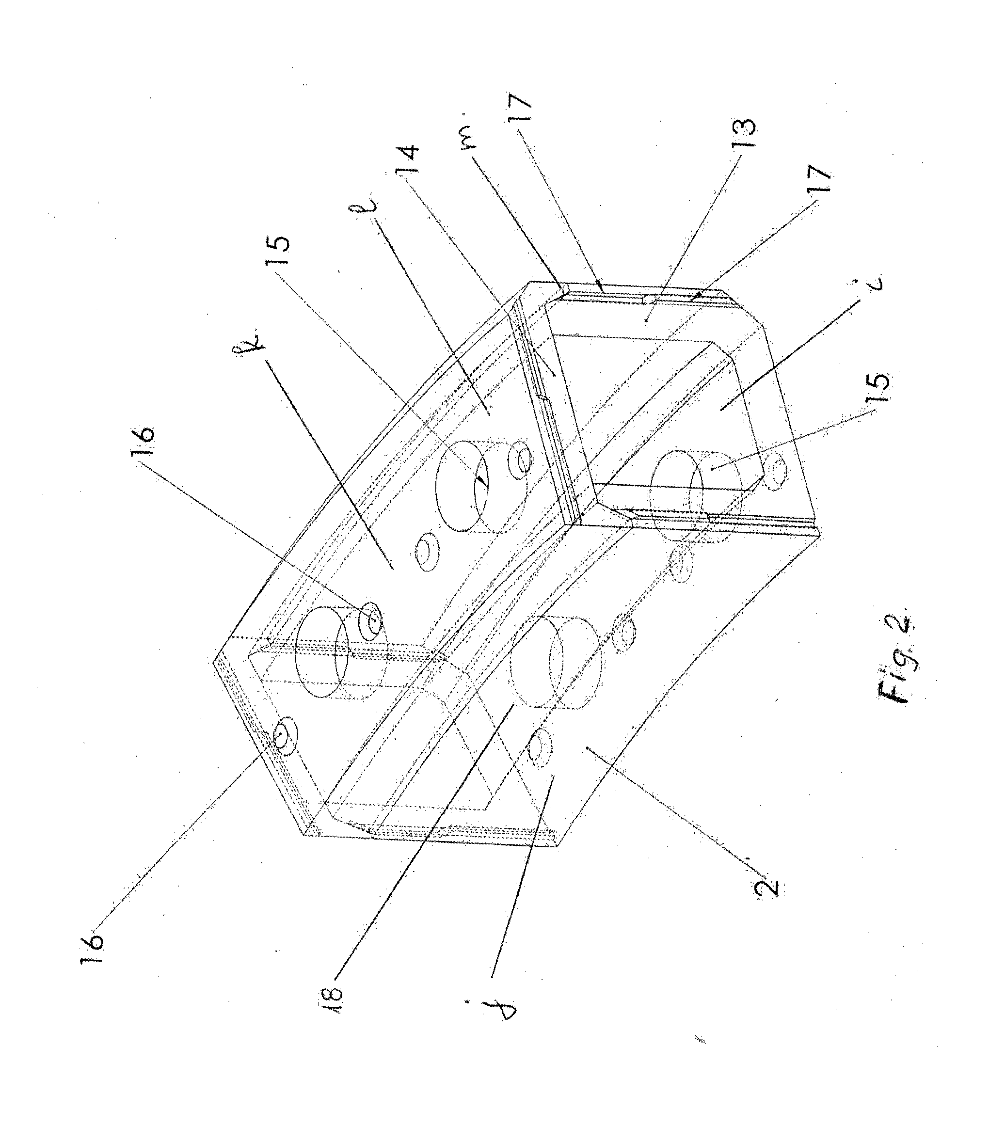
[0047]A circular basin with a volume of 200 m3 is built for the storage of hot water needed for heating a living space during the cold season. Twenty two modular elements of polyurethane foam are used for each row. The first annular row (ring) of twenty two U profiles 13 is placed. A reinforcement comprising four striated steel for reinforced concrete bars with a diameter of 20 mm, fastened with clamps with a diameter of 8 mm is assembled in compartments 18, and vertical reinforcements of four steel for reinforced concrete bars with a diameter of 14 mm, fastened with circular clamps with a diameter of 6 mm, are also assembled starting from each channel 15. Polyurethane plates with 24 cm thickness are laid, forming the insulation 3 of the bottom of the basin. Increased resistance concrete (C20 / 25) is cast in the compartments 18 and over the basin bottom insulation 3, in a layer of 10 cm thickness, forming the concrete foundation 7. The lids 14 are placed on top of U profiles 13.

[0048...

embodiment 2

Storage Basin “Tank in Tank”

[0050]Two concentric basins for storage of hot water are built. The exterior basin has twenty two modular elements on each annular row and the interior one has fifteen modular elements on each annular row. The water in the interior tank is warmer than the water in the exterior tank. The heat of the water from the interior tank is not wasted through the vertical wall of said tank, but it changes into absorbed heat for the water in the exterior tank. The heat of the water with higher temperature (80-90° C.) from the interior tank is used to obtain hot house water and the heat of the water with a lower temperature (70-80° C.) from the exterior tank is used for heating a living space.

[0051]The construction of the “tank in tank” basin is similar to embodiment 1. The first concentric annular rows are placed, using thirty seven U profiles 13, the bottom of the basin is insulated with polyurethane plates 24 cm thick, reinforcements of steel for reinforced concret...


PUM

PropertyMeasurementUnit
angleaaaaaaaaaa
diameteraaaaaaaaaa
diameteraaaaaaaaaa

Abstract

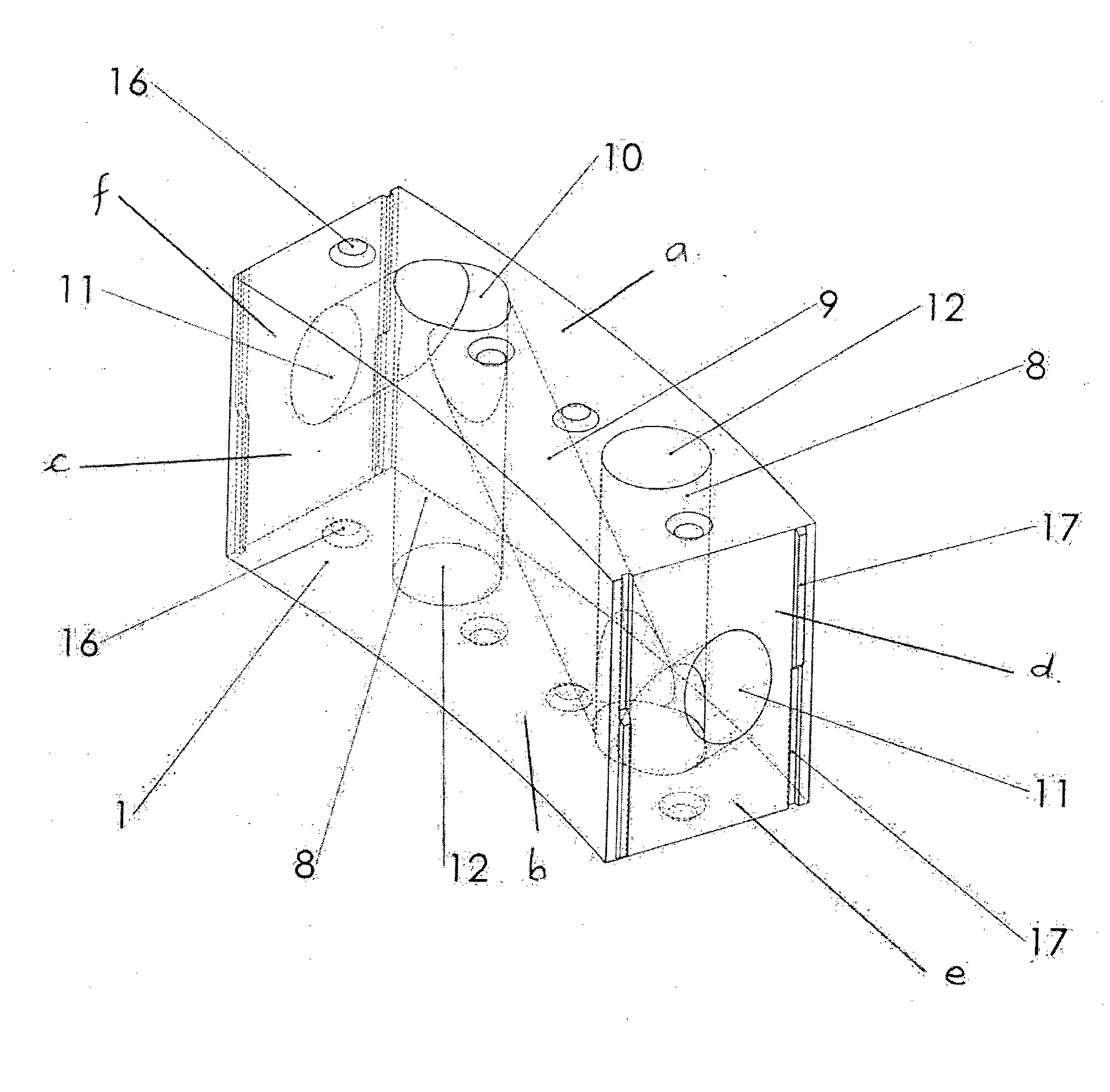
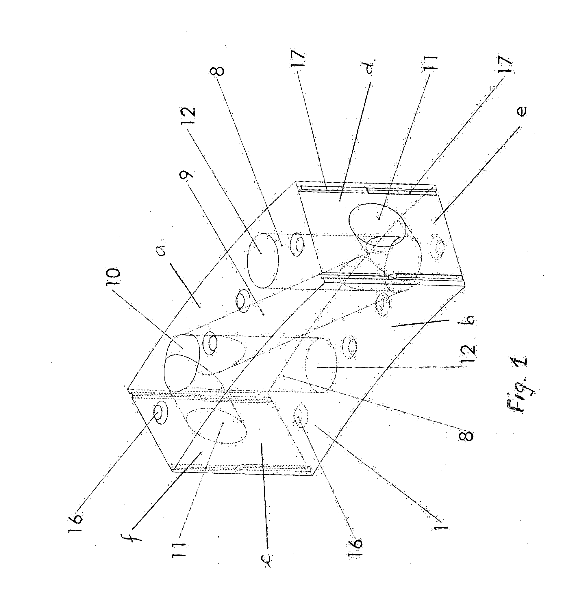
The invention relates to modular elements for building a storage basin, to a network obtained by assembling a plurality of modular elements, to a supporting structure, to a storage basin and to a process for obtaining a storage basin. The modular element according to the invention is provided in the interior with a network element constituted by main half joints (10), secondary half joints (11) and tertiary half joints (10), vertical channels (8,15), oblique channels (9), compartments (18), and is provided with joint elements (16,17). The network comprises horizontal annular channels and main, secondary and tertiary joints connected by vertical and oblique channels. The storage basin comprises a supporting structure at the interior of an insulating structure obtained by assembling the modular elements. The process for obtaining a storage basin comprises the assemblage of the modular elements and casting the hardening material in the network obtained by assembling the modular elements, forming the supporting structure.

Description

TECHNICAL FIELD[0001]The invention relates to modular elements made of insulating material for building storage basins, made of insulating materials, comprising at the interior at least one network element, to a network obtained by assemblying the modular elements, to a supporting structure and to a process for building a storage basin by assemblying the modular elements.BACKGROUND ART[0002]The patent US2002017070 describes an expanded plastic module destined for building an insulated concrete wall structure, by assembling the modules and filling them with concrete. For example, the module is made of expanded polystyrene.[0003]Each module has the form of a rigid block, having an interior configuration designed to be filled with concrete. Additionally, for increasing the strength, a network of steel or plastic bars is being introduced inside the modules. The disadvantage of this technical solution consists in a high rate of concrete consumption, flow problems when casting the concret...

Claims


Application Information

Patent Timeline
Patent Type & Authority Applications(United States)
IPC IPC(8): B65D81/38B65D81/18
CPCB65D81/18B65D81/3825E04B2/18E04B2/22E04B2/26E04B2/32E04B2/36E04H7/18E04B2002/0221E04B2002/0265B65D90/024B65D90/028Y10T29/4998
Inventor BREAZ, LAURENTIU DUMITRU
Owner BREAZ LAUREN&TCEDIL IU DUMITRU
Why Eureka
Try Eureka