System for measuring noise figure of a radio frequency device

a radio frequency device and noise figure technology, applied in the direction of noise figure or signal-to-noise ratio measurement, instruments, resistance/reactance/impedence, etc., can solve the problem of not always practical to test the device under test, and generate the same amount of noise power

Inactive Publication Date: 2000-09-05
CREDENCE SYSTEMS
View PDF4 Cites 23 Cited by
  • Summary
  • Abstract
  • Description
  • Claims
  • Application Information

AI Technical Summary

Problems solved by technology

A resistor of any size will generate the same amount of noise power.
While the standard precisely defines F, it is not always practical to test a device under test (DUT) for noise figure F by applying the signal produced by a resistor held at 290 degrees K as a test signal input to a DUT.

Method used


Image

  • System for measuring noise figure of a radio frequency device
  • System for measuring noise figure of a radio frequency device
  • System for measuring noise figure of a radio frequency device

Examples


Embodiment Construction

)

Noise Figure Definition

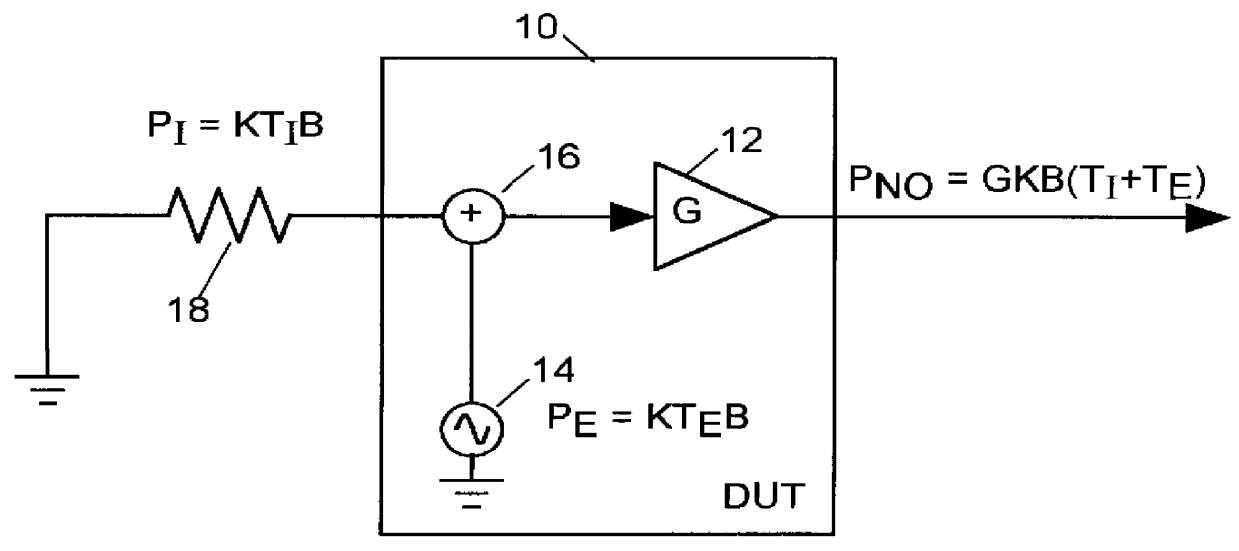
Noise figure F is a commonly used measure of the noise produced by radio frequency device under test (DUT). Noise figure is defined as

F=1+(P.sub.NO -GP.sub.0) / GP.sub.O [19]

where G is the gain of the DUT, and P.sub.NO is the output signal power the DUT would produce within some narrow frequency band of the radio frequency spectrum when the DUT is stimulated by a test signal having power P.sub.0 in that frequency band. In particular the test signal power P.sub.0 is defined as the power produced by a resistor at 290 degrees K within that narrow band of the radio frequency spectrum,

Within any narrow band of width B in the radio frequency spectrum, a resistor held at some temperature T produces a noise signal having a power P in any part of the radio frequency spectrum of bandwidth B of

P=kTB [20]

where K is Boltzmann's constant. Since resistor noise power P.sub.0 produced by a resistor at 290 degrees Kelvin is relatively small and predictable, it can make a suitabl...


PUM


Abstract

Noise factor of a radio-frequency device under test (DUT) is determined by driving the input of the DUT with a randomly modulated sine wave and measuring the power of a resulting DUT OUTPUT signal within each of a set of equally-sized frequency bands. The noise factor is computed as a combination of the power of the modulated sine wave within each of a plurality of frequency bands and the measured power of the DUT OUTPUT signal within that same plurality of frequency bands.

Description

1. Field of the InventionThe present invention relates in general to systems for measuring the noise figure of a radio frequency device and in particular to a system for measuring noise figure employing a randomly modulated signal as a device stimulus.2. Description of Related ArtNoise figure F, a commonly used measure of the noise produced by radio frequency devices, is defined as the signal-to-noise ratio P.sub.SI / P.sub.NI of the device's input signal divided by the signal-to-noise ratio P.sub.SO / P.sub.NO of the device's output signal:F=(P.sub.SI / P.sub.NI) / (P.sub.S0 / P.sub.N0) [1]An electronic device has a gain (or loss) G whereG=P.sub.SO / P.sub.SI [2]The output signal noise P.sub.NO of any device includes a component GP.sub.NI, the amplified noise in the device's input signal, and an "added noise" component P.sub.NA generated by the device itself:P.sub.NO =GP.sub.NI +P.sub.NA [3]From equations [1]-[3] we have:F=1+P.sub.NA / GP.sub.NI [4]From equation [4] we see that the value o...

Claims


Application Information

Patent Timeline
Patent Type & Authority Patents(United States)
IPC IPC(8): G01R29/00G01R29/26
CPCG01R29/26
Inventor KASTEN, JEFFERY SCOTT
Owner CREDENCE SYSTEMS
Why Eureka
Try Eureka