Containment area process

a technology for containment areas and containment areas, which is applied in the direction of sludge treatment by dewatering/drying/thickening, machines/dredgers working methods, and construction. it can solve the problems of hazardous spoil classified as hazardous, no new containment areas are being built for the disposal of this spoil, and the difficulty of construction of interior ditches

Inactive Publication Date: 2000-09-19
WILCO MARSH BUGGIES & DRAGLINES
View PDF11 Cites 24 Cited by
  • Summary
  • Abstract
  • Description
  • Claims
  • Application Information

AI Technical Summary

Problems solved by technology

This spoil is classified as hazardous by the EPA since, for example, the sludge dredged from waterways contains oil and other heavy metals which have sunk to the bottom of the waterway.
Since this spoil has been classified as hazardous waste and because the land used for a containment area thereafter becomes unusable for any other purpose, no new containment areas are currently being built for the disposal of this spoil.
Because they cross the pit of the containment area, the interior ditches have proven difficult to construct.
The pit of the containment area is difficult for equipment to operate in because the spoil is pumped into the containment area is in the form of a slush or sludge which provides little or no ground support.
These tires permit the digging vehicle to remain "afloat" in the spoil, but, unfortunately, they do not provide sufficient traction in wet spoil so that ditches can be dug.
This procedure is very slow and labor intensive.
These attempts have largely been unsuccessful.
However, the torque designed for the hydraulic winch can easily be exceeded in pulling the digging vehicle such that the bypass may not be affected.
It has been observed that a 1 / 2 inch cable wrapped on the spool of a hydraulic winch was not strong enough to pull a ditching vehicle across the containment area and would often break.
However, each additional wrap on the spool reduced the line pull of the hydraulic winch.
This procedure is cumbersome, requires a separate spool for the cable, and oftentimes does not have sufficient torque to pull the digging vehicle across the containment area.
There is no known hydraulic winch which is capable of providing 60,000 lbs. of line pull using 12,000 feet of cable.

Method used


Image

  • Containment area process
  • Containment area process
  • Containment area process

Examples


Embodiment Construction

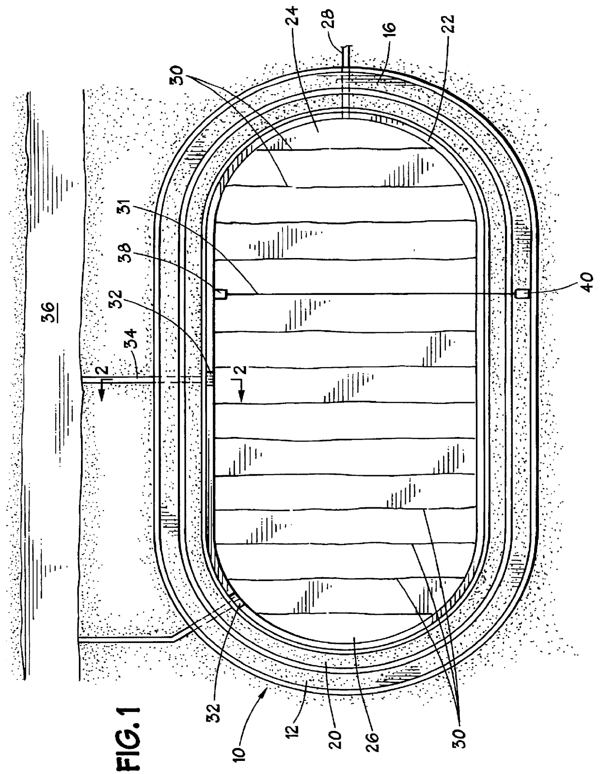
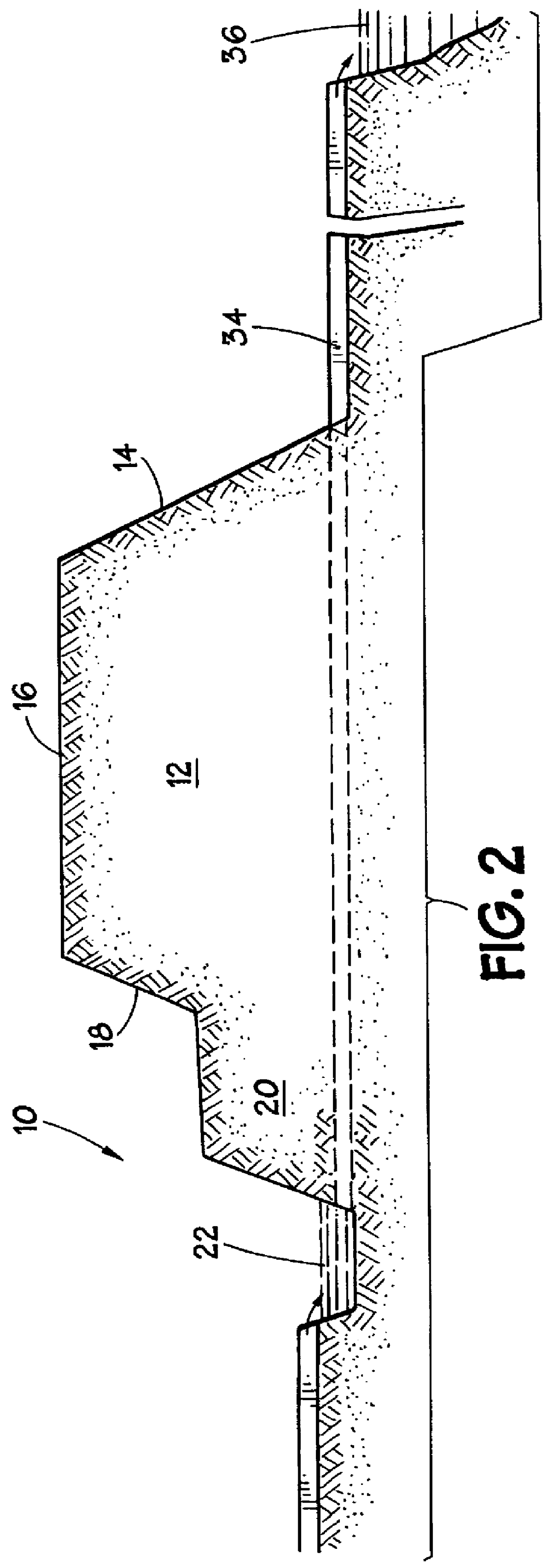
Referring initially to FIGS. 1 and 2, there is shown the disposal area or containment area 10 having a levy 12 extending around its perimeter. Levy 12 includes an outer slope 14, a crown 16, and an inner slope 18 down to a berm 20. Berm 20 also slopes down into the containment area 10. A perimeter ditch 22 extends around the perimeter of containment area 10 adjacent to berm 20 and levy 12. Typically, one end 24 of containment area 10 is higher than the other end 26. The slope between high end 24 and low end 26 is typically two feet. Spoil, such as sludge, slush, or spent ore, or other waste flows or is pumped through a pipe 28 into high end 24 of containment area 10.

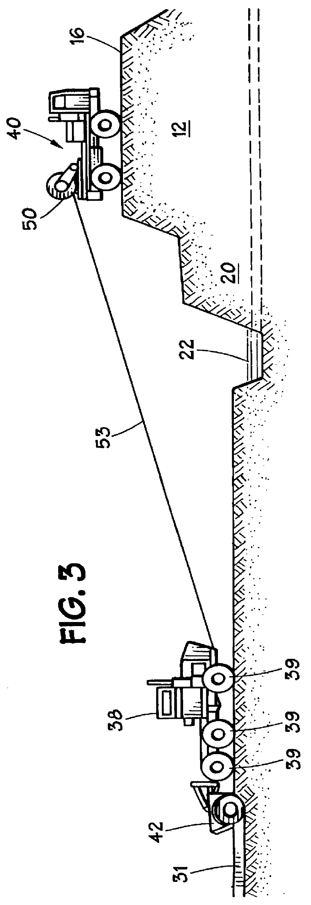
Dewatering and Drying of Spoil in the Containment Area Pit

According to methods of the present invention, a plurality of interior ditches 30 must be dug which extend across the width of containment area 10 which are sloped and extend to the perimeter ditch 22 for dewatering via drainage of the water in the spoil to perime...


PUM

PropertyMeasurementUnit
thickaaaaaaaaaa
thickaaaaaaaaaa
widthaaaaaaaaaa

Abstract

Effective techniques and equipment are described for maintaining and improving dredge disposal sites. In one aspect, the use of winching equipment is described to move a digging vehicle within a containment area for effective creation of ditching to permit substantial dewatering and drainage of the dredge spoil to dry it. Substantially dried spoil is removed from the containment area pit using amphibious scraper equipment. The substantially dried spoil may then be used to build up the berm surrounding the dredge pit.

Description

1. Field of the InventionThe present invention relates to methods and apparatus for maintenance and improvement of dredge disposal containment areas. In one particular aspect, the invention relates to methods and apparatus for constructing ditching in low ground pressure areas such as containment areas for dewatering and drying of spoil. In another particular aspect, the invention relates to methods and apparatus for removing the dried spoil from the containment area.2. Description of the Related ArtDredge disposal or containment areas are located throughout the United States for the disposal of dredge spoil which has been dredged from waterways or spent ore or waste from mining operations. This spoil is classified as hazardous by the EPA since, for example, the sludge dredged from waterways contains oil and other heavy metals which have sunk to the bottom of the waterway. Since this spoil has been classified as hazardous waste and because the land used for a containment area therea...

Claims


Application Information

Patent Timeline
Patent Type & Authority Patents(United States)
IPC IPC(8): B09B1/00C02F11/12E02F9/02E02F9/20E02F5/00E02F3/64E02F3/65E02F5/02
CPCB09B1/00C02F11/12E02F3/6454E02F3/65E02F5/006E02F5/02E02F5/025E02F9/024E02F9/028E02F9/2016
Inventor WILSON, SR., JOHN M.WILSON, DEAN R.
Owner WILCO MARSH BUGGIES & DRAGLINES
Why Eureka
Try Eureka