Recording medium cartridge with a twin-coiled torsional spring-biased shutter

Inactive Publication Date: 2000-09-26
MAXELL HLDG LTD
View PDF14 Cites 22 Cited by
  • Summary
  • Abstract
  • Description
  • Claims
  • Application Information

AI Technical Summary

Problems solved by technology

Although any possible ingress of dusts into the tape chamber is effectively and advantageously avoided, the pivotally supported shutter poses a problem in that when the shutter is opened against the biasing force of the torsional spring, the shutter protrudes a considerable distance outwardly of the housing, particularly outwardly from the front wall of the housing.
Considering that opening of the shutter is mainly required when the tape cartridge is loaded in a tape drive, the freedom of disposition of a tape loading mechanism and a tape transport mechanism in the tape drive is limited and a relatively large space has to be secured within the tape drive to accommodate the shutter then in the opened position.
This not only restricts the freedom of design, but also hampers downsizing and simplification of the tape drive and increase of the tape transport speed.
When it comes to the slide shutter required to travel a substantial distance between the closed and opened positions, difficulties would be often encountered in choosing the biasing member for biasing the slide shutter normally towards the closed position and, also, optimizing the biasing force of such biasing member regardless of the position thereof between the closed and opened positions.
However, if such torsional spring is used in association with the increased stroke of movement of the slide shutter, the single-coiled torsional spring of a given size would exerts an insufficient biasing force with the spring arms expanding in respective directions away from each other.
In other words, for a given size and design of the single-coiled torsional spring, the use thereof in association with the slide shutter is limited w

Method used


Image

  • Recording medium cartridge with a twin-coiled torsional spring-biased shutter
  • Recording medium cartridge with a twin-coiled torsional spring-biased shutter
  • Recording medium cartridge with a twin-coiled torsional spring-biased shutter

Examples


first embodiment-- figs.1 to 6

First Embodiment--FIGS. 1 to 6

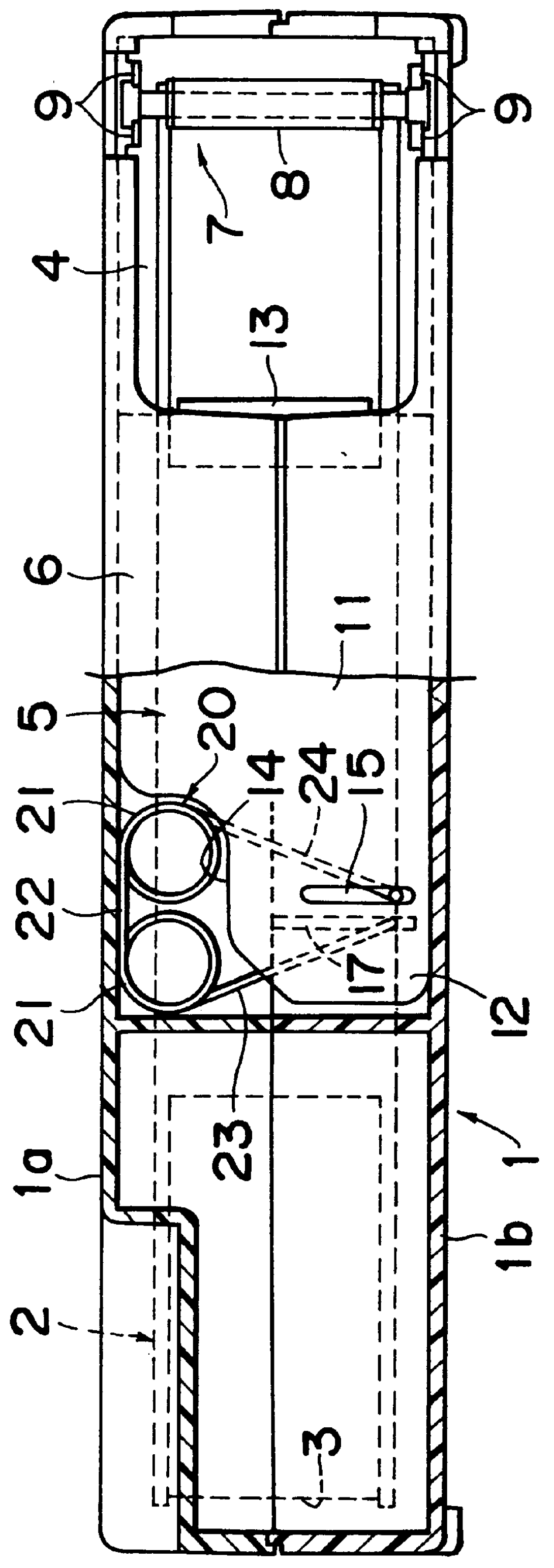
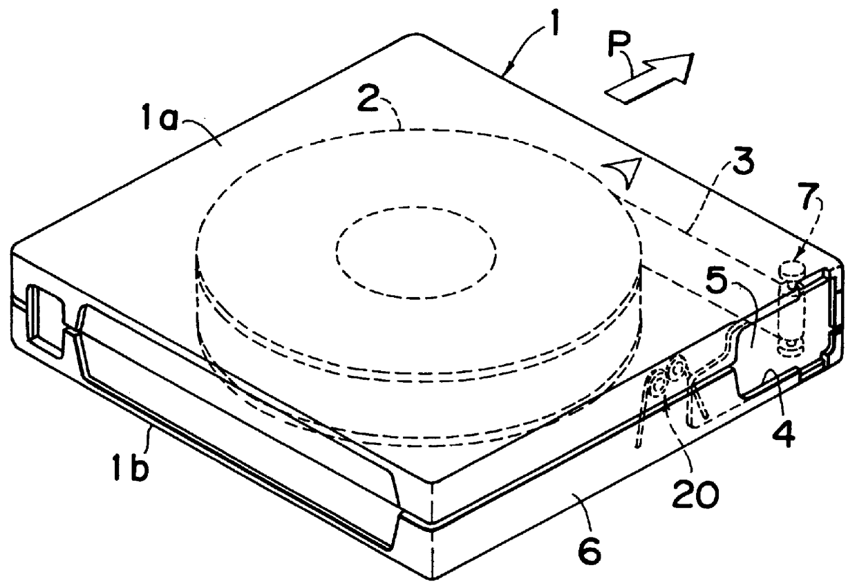
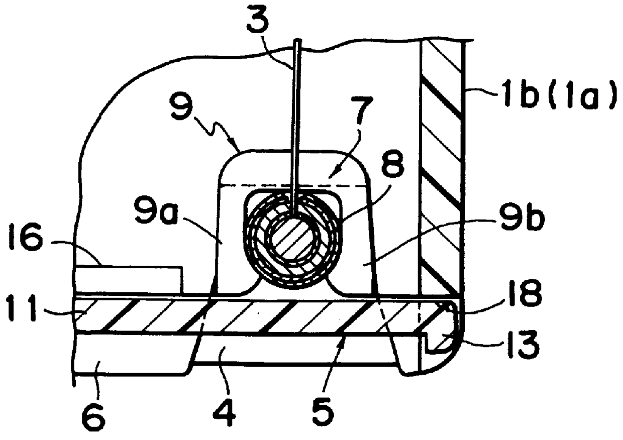
Referring first to FIGS. 1 to 6, there is shown a first preferred embodiment of the present invention which is directed to a single-reel magnetic tape cartridge. As best shown in FIG. 2, the single-reel magnetic tape cartridge comprises a generally rectangular box-like housing 1 made up of upper and lower casings 1a and 1b joined together in any known manner to define a tape chamber. The housing 1 so formed includes top and bottom panels, a peripheral front wall 6, a peripheral rear wall opposite to the front wall 6 and first and second peripheral side walls opposite to each other and accommodates therein a single reel 2 around which a length of magnetic tape 3 is wound. When in use with a tape drive such as, for example, used in association with a computer, the single-reel magnetic tape cartridge is loaded into the tape drive in a direction shown by the arrow P with one of the side walls, for example, the first side wall of the housing 1 oriented towar...

second embodiment-- figs.7 to 11

Second Embodiment--FIGS. 7 to 11

Referring to FIGS. 7 to 11, there is shown a second preferred embodiment of the present invention which is directed to a disc cartridge accommodating therein a magneto-optical recording disc 30. As shown in FIGS. 7 and 8, the disc cartridge comprises a generally square box-like flat housing 1 made up of upper and lower casings 1a and 1b joined together in any known manner to define a disc chamber. The housing 1 so formed includes top and bottom panels 31a and 31b, a peripheral front wall 6, a peripheral rear wall opposite to the front wall 6 and first and second peripheral side walls opposite to each other and accommodates therein the magneto-optical disc 30.

The top and bottom panels of the housing 1 has an access window 44 defined therein at a respective location adjacent the front wall 6 and substantially intermediate of the length of the front wall 6 (or the width of the housing 1). The respective access windows 44 in the top and bottom panels are ...

second embodiment

While the disc cartridge according to the present invention has been fully described, it is to be noted that various changes and modifications are apparent to those skilled in the art. For example, although in the foregoing embodiment the twin-coiled torsional spring 20 has been shown as accommodated within the front left corner area D, it may be accommodated within the front right corner area D as viewed in FIGS. 7 and 8. Also, the disc 30 may be any known disc-shaped recording medium such as a magnetic disc, an optical disc or a magneto-optical disc. Moreover, the direction of insertion of the disc cartridge may not be limited to the direction shown by the arrow P, but the disc cartridge embodying the present invention may be inserted in the disc drive with, for example, the front wall 6 oriented towards the disc drive. Yet, the corner 36 may not be angled as shown, but may be right-angled or rounded.

Although the present invention has been described in connection with the preferre...


PUM


Abstract

A cartridge includes a housing having a medium chamber defined therein for accommodating the recording medium and also having at least one access opening defined therein, a slide shutter slidably mounted on the housing for movement between an opened position in which the access opening is opened and a closed position in which the access opening is closed, and a biasing member for biasing the slide shutter towards the closed position. The biasing member is in the form of a twin-coiled torsional spring including first and second coils connected together by means of a bridge and first and second spring arms extending outwardly from the first and second coils, respectively. The first spring arms has a free end engaged to the slide shutter and the second spring arm has a free end engaged to a portion of the housing.

Description

1. Field of the InventionThe present invention relates to a cartridge accommodating therein an information carrier medium which may be a length of magnetic recording tape, a magnetic recording disc, an optical disc or a magneto-optical disc.2. Description of the Prior ArtThe cartridge for accommodating the information carrier medium is currently available in various types. Of those types, the present invention pertains to a single-reel tape cartridge generally used in association with a computer for data back-up purposes, a compact two-reel tape cartridge generally known as a DAT (digital audio tape) cartridge, and a disc cartridge. In any event, the present invention is applicable to any type of cartridge having a spring-biased slide shutter.As is well known to those skilled in the art, the single-reel tape cartridge comprises a generally rectangular box-like housing having top and bottom panels and a peripheral wall Including front, rear and side walls and joining the top and bott...

Claims


Application Information

Patent Timeline
IPC IPC(8): G11B23/107G11B23/04G11B23/03G11B23/08G11B23/033
CPCG11B23/0308G11B23/045G11B23/107G11B23/03
Inventor MIYAZAKI, NOBUTAKASUMIDA, TAKASHI
Owner MAXELL HLDG LTD
Why Eureka
Try Eureka