Pruning saw

a sawing saw and saw blade technology, applied in the field of pruning saws, can solve the problems that the pruning saws of the type mentioned above according to prior art do not meet the needs and requirements well enough, and achieve the effects of fast and efficient sawing, improved pruning, and efficient chip removal from the ker

Inactive Publication Date: 2000-10-03
SANDVIK AB
View PDF7 Cites 63 Cited by
  • Summary
  • Abstract
  • Description
  • Claims
  • Application Information

AI Technical Summary

Benefits of technology

Pruning saws of the type mentioned above according to prior art do not fill the needs and requirements well enough. The present invention aims to create an improved pruning saw. One fundamental aim of the invention is thus to create a pruning saw which will ensure efficient chip removal from the kerf and permit fast and efficient sawing with minimal

Problems solved by technology

Pruning saws of the type mentioned above according to pri

Method used


Image

  • Pruning saw
  • Pruning saw
  • Pruning saw

Examples


Embodiment Construction

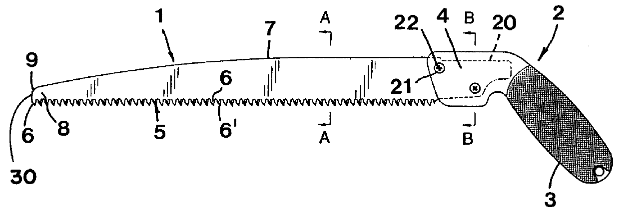
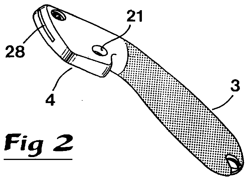
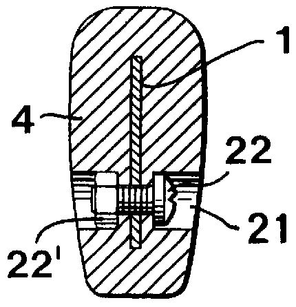
The pruning saw shown in FIG. 1 comprises an elongated blade (1) and a handle unit (2). This handle comprises a gripping part (3) and an attachment part (4) connected to a rear mounting portion of the saw blade. A cutting portion of the blade projects longitudinally forwardly from the handle and has a line of teeth (5), that forms a longitudinal toothed edge. The line of teeth comprises a multitude of teeth (6, 6') of equal shape. Preferably, the teeth should have equal size and equal distance for simplest manufacture. A back edge (7) of the blade is situated opposite to the line of teeth (5).

In the shown embodiment the back edge (7) extends straight and parallel to the line of teeth (5) from the handle to a point at a certain distance from the handle, the blade having a maximum height here. From here, the back edge (7) is somewhat curved, tapering down to near the free end front region. At the front end the back edge turns into a convexly rounded edge portion (9) which via a short ...


PUM

PropertyMeasurementUnit
Angleaaaaaaaaaa
Angleaaaaaaaaaa
Shapeaaaaaaaaaa

Abstract

A pruning saw includes an elongated sawblade which has a line of cutting teeth. Opposite sides of the blade extending between the line of teeth and the back edge are concave. A thinnest waist between the concave sides is located closer to the line of teeth than to the back where the blade has its maximum height. A front edge of the blade forms a rounded corner where it intersects the back edge.

Description

FIELD OF APPLICATION OF THE INVENTIONThis invention concerns a pruning saw of the kind comprising an elongated saw blade, which is connected at one end to a handle and which has along its whole length a uniform line of teeth with homologous and equidistantly located teeth, where both faces of the blade between the line of teeth and an opposing back edge have a slightly concave shape and where an individual tooth has front and rear cutting edges formed by the intersection of a flat face with two obliquely ground surfaces, each of which extends at an angle to the faces, and where an individual gullet between two teeth is rounded and extends at right angle to the plane of the faces.Handsaws of the type called pruning saws by craftsmen are used not only for non-professional gardening but also professionally such as for pruning of growing plants in vineyards, large fruit orchards or similar. Lately, the increasing use for such purposes has led to stringent requirements for such saws whic...

Claims


Application Information

Patent Timeline
IPC IPC(8): A01G3/00A01G3/08B27B21/00B27B21/04B27B33/10B23D49/11B23D61/12
CPCB27B21/04A01G3/08Y10T83/9319
Inventor ERIKSSON, ECKHARDLUND, NILS-ERIK
Owner SANDVIK AB
Why Eureka
Try Eureka