Interconnect system for heating conductors in an aircraft

an interconnection system and heating conductor technology, applied in the direction of electrical equipment, heater elements, coupling device connections, etc., can solve the problems of non-uniform and unwieldy geometry, complicated connection process, and inability to meet the requirements of the application

Inactive Publication Date: 2000-10-03
DAIMLER CHRYSLER AEROSPACE AIRBUS
View PDF14 Cites 22 Cited by
  • Summary
  • Abstract
  • Description
  • Claims
  • Application Information

AI Technical Summary

Problems solved by technology

These liquid-containing components are subject to freezing temperatures during the operation of the aircraft.
The heater band interconnection carried out in the above described manner results in a non-uniform and unwieldy geometry and involves several applications of an adhesive potting compound and plural shrinkable tubes forming sheaths.
The process for forming the connection is rather complicated and time consuming because the connection structure is formed by manually applying the adhesive potting compound, and then fitting several shrinkable tubes thereon, and finally individually drying and curing each adhesive potting compound layer separately in an oven.
There is also a danger that a uniform and constant quality cannot be achieved over a series of connections, whereby the sealing properties may be negatively influenced at the extreme low pressure conditions and drastic temperature variations that prevail in the aircraft.
Moreover, a danger exists that the applied shrinkable tubes may crack or tear at various offset or shouldered or stepped locations of the non-uniform geometry.
In that case, the sealing of the heater band interconnection, as well as the reliability of the heater band overall, will consequently be negatively influenced, whereby the power supply reliability of an entire integrated heating conductor interconnection system can be jeopardized.
Moreover, the above described conventional technology suffers the disadvantage that the electrical conductors of the heater band, without the protective conductor braid, are functionally laid out as extension conductors.
The above described conventional measures require a considerable amount of time, effort and expense.
Moreover, the danger exists that one or more strands of the conductor will be damaged, and the surface protection can be damaged.
The manual application of the adhesive potting compound onto the conductors and the subsequent sliding or pushing of the shrinkable tubes onto the arrangement also add to the technological effort and expense.
As a further disadvantage, the electrical assembly of the protective conductor braid and the additional extension conductor by means of a respective butt connector does not exactly define the position and the integration of this assembly within the heater band connection.
Therefore, and since the butt connector includes a through-going axial hole, it is not possible to avoid a complete or 100% capillary action through the crimped butt connector.
The multiple drying and curing steps required by the adhesive potting compound for adhesively bonding the shrinkable tubes by means of heating in an oven further add to the technical complexity, effort and expense.
A final heat treatment for an additional outer shrinkable tube or sheath, which provides additional sealing and the outer mechanical protection of the prepared heater band connection, further considerably increases the technological effort and expense.
For the above reasons, heater band connections cannot be economically and practically produced according to the methods and arrangements of the prior art.
Moreover, the heater bands to be installed in an aircraft cannot be economically pre-fabricated according to the above described state of the art.

Method used


Image

  • Interconnect system for heating conductors in an aircraft
  • Interconnect system for heating conductors in an aircraft
  • Interconnect system for heating conductors in an aircraft

Examples


Embodiment Construction

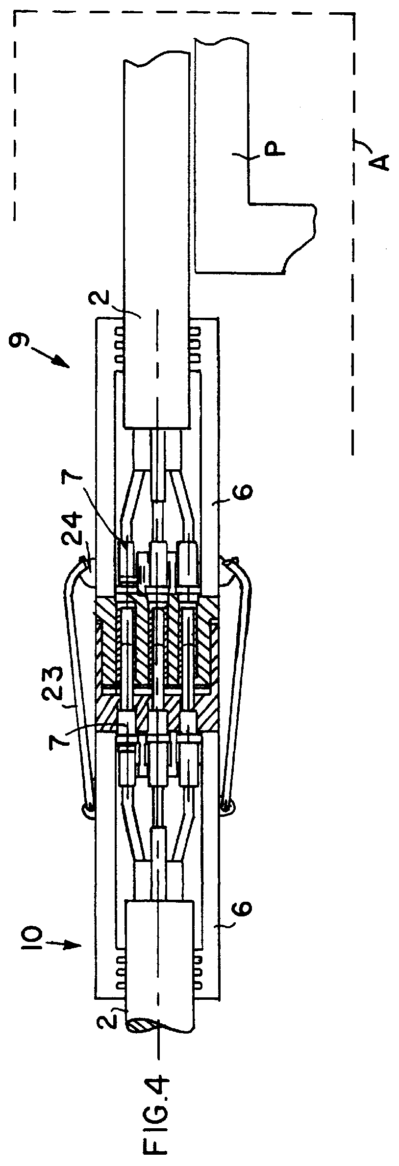
A heating conductor interconnection system can be installed in an aircraft to provide prophylactic freeze protection and product heating, of frost endangered pipes or conduit systems and their related accessories. Such a heating cable system is particularly applicable, for example, for heating the fresh water supply system and the waste water drain system to prevent freezing of the water therein. The heating conductor interconnection system is embodied in such a manner that any defective or failing individual section or component thereof may simply and without problems be removed from the system and be replaced by a properly functioning component.

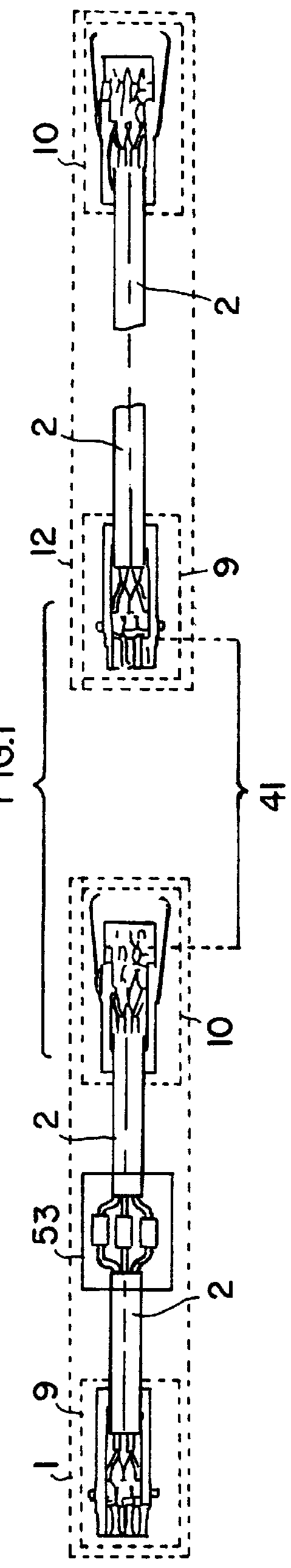
The heating conductor interconnection system as shown in FIG. 1 includes a first heating conductor arrangement or heater unit 1 and a second heating conductor arrangement or heater unit 12, which are arranged end-to-end adjacent one another and may be electrically coupled and mechanically locked together in a coupling region 41, by means of...


PUM


Abstract

A system of interconnected heating conductors, suitable for preventing freezing of water lines in an aircraft for example, includes a plurality of heater units (1, 12) electrically coupled together by respective coupling plugs (9, 10). Each heater unit comprises one or more heating conductor bands or cables (2, 21, 22), with a respective socket contact plug (9) connected to one end thereof and a respective pin contact plug (10) connected to the other end thereof. Each plug (9, 10) includes a housing (6) wherein the conductors of the heater band (2) are crimp-connected to electrical connectors (7), which include pin contacts (723) in the case of the pin contact plug (10) and socket contacts (77) in the case of the socket contact plug (9). The housing (6) is completely filled with a sealing compound (19) which is injected through a fill hole in the housing wall. The pin contacts (723) extend outwardly through contact chambers into a female cavity (411) of the plug (10), while the socket contacts (77) extend outwardly through contact chambers in a male plug member (412) of the plug (9). The two plugs may be matingly plugged together, and mechanically secured by locking bails (23) engaging retaining catches (24). This achieves a very effective seal against moisture penetration, and eliminates capillary action even when subjected to vibrations, shock, temperature variations, and low pressure conditions.

Description

PRIORITY CLAIMThis application is based on and claims the priority under 35 U.S.C. .sctn.119 of German Patent Application 197 26 419.0, filed on Jun. 23, 1997. The entire disclosure of German Patent Application 197 26 419.0 is incorporated herein by reference.The invention relates to a system for interconnecting heating conductors such as heater bands, cables, tapes or strips, including a plurality of heating conductor arrangements that are electrically coupled together by means of respective electrical coupling elements, especially in an aircraft.BACKGROUND INFORMATIONModern aircraft include various different systems of pipes, conduits, instruments, and accessories in which various liquid products are transported. These liquid-containing components are subject to freezing temperatures during the operation of the aircraft. Therefore, it has become generally known to apply interconnected heater bands, cables, tapes, or strips (generally called heater bands herein) onto these liquid-c...

Claims


Application Information

Patent Timeline
Patent Type & Authority Patents(United States)
IPC IPC(8): B64D15/00B64D15/12H01R13/52H01R13/639
CPCB64D15/12H01R13/6392H01R13/5221H01R2107/00
Inventor KIRMA, SAFASTOEVER, HEINZPFEIFF, JOACHIMERDMANN, WOLFGANG
Owner DAIMLER CHRYSLER AEROSPACE AIRBUS
Why Eureka
Try Eureka