Rupture disk controlled mechanically actuated pressure relief valve assembly

Inactive Publication Date: 2000-10-17
FIKE CORP
View PDF14 Cites 50 Cited by
  • Summary
  • Abstract
  • Description
  • Claims
  • Application Information

AI Technical Summary

Benefits of technology

am of the failed control valve. An advantage of the present invention in such situations is that replacement of the bypass valve rupture disk is a simple matter which can be readily accomplished without the need for dismantling conduits or other complicated operations. Moreover, because of the use of rupture disks in accor

Problems solved by technology

Such lines are equipped with butterfly control valves which, if they become jammed or inoperative, can lead to catastrophic failures and explosions.
The use of in-line burst disks as pressure relief devices in flare bypass arrangements, while safe and effective, requires a relatively complex operation to change out a burst disk.
Thus, disk replacement requires unbolting of the bypass piping which can result in spillage of fluids and consequent plant contamination.
These difficulties are even more pronounced in the case of large bypass units (e.g., 24-36 inch piping) having correspondingly large disks.
Furthermore, in large scale bypass assemblies, the cost of replacement rupture disks becomes significant.
A significant problem with collapsing pin valve designs is the difficulty in retrofitting the valves to alter the set point pressure thereof.
This becom

Method used


Image

  • Rupture disk controlled mechanically actuated pressure relief valve assembly
  • Rupture disk controlled mechanically actuated pressure relief valve assembly
  • Rupture disk controlled mechanically actuated pressure relief valve assembly

Examples


Embodiment Construction

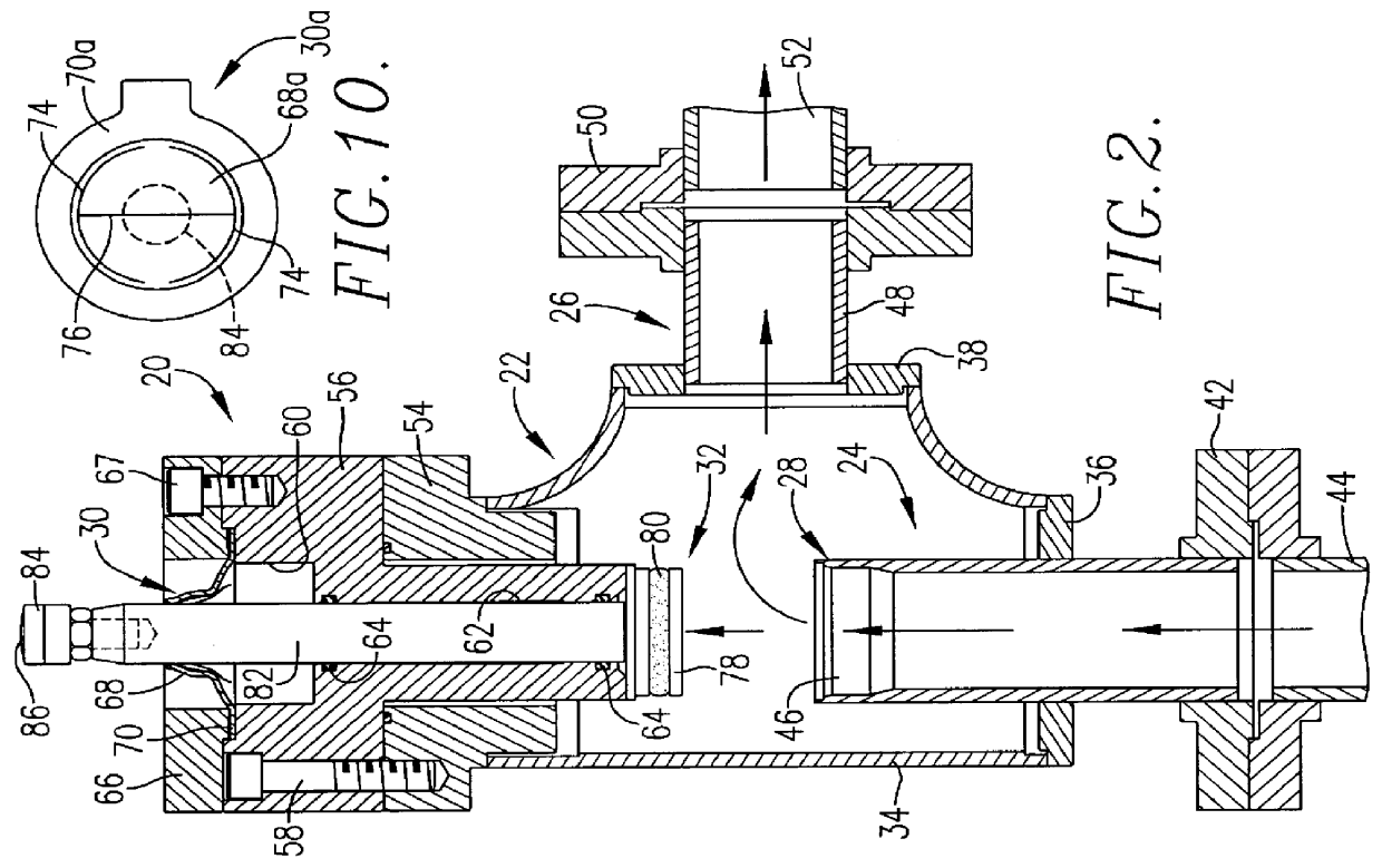
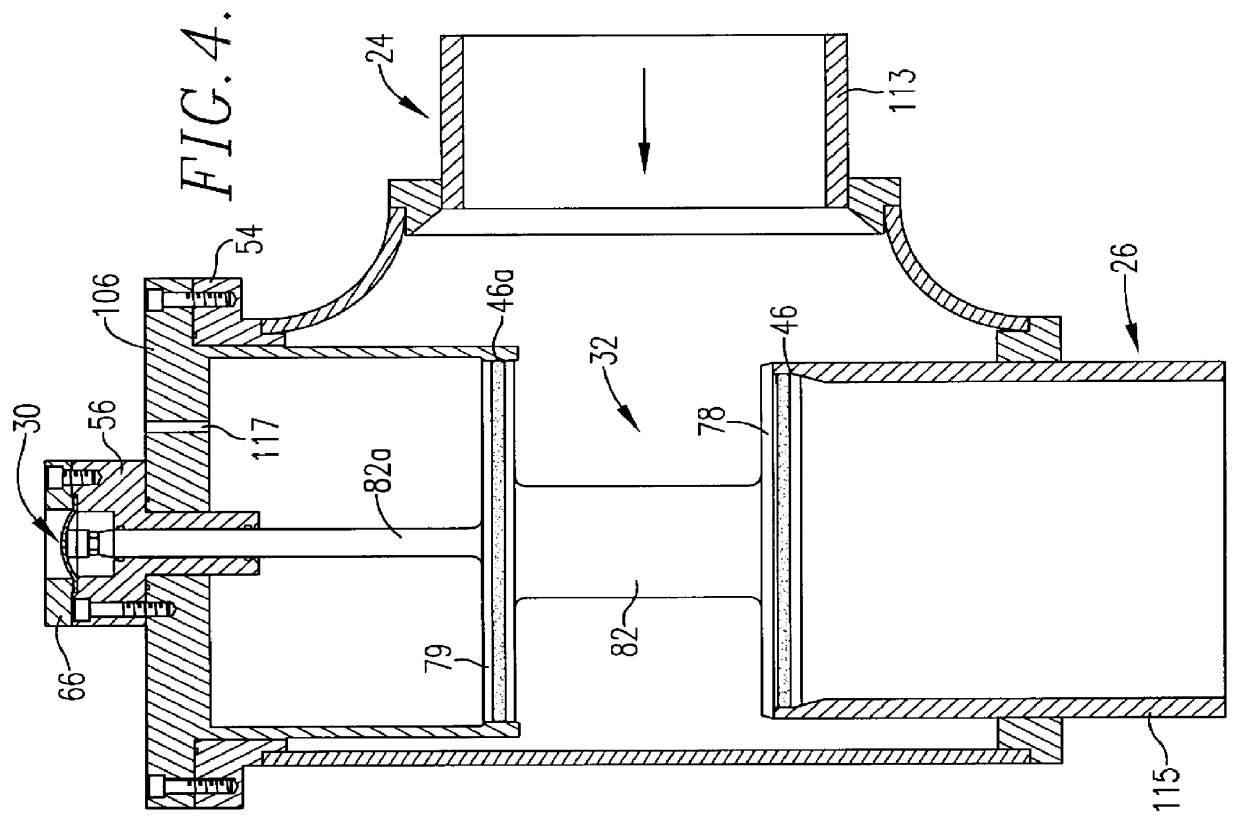
Turning now to the drawings and particularly FIGS. 1 and 2, a pressure responsive relief valve assembly 20 is illustrated. The valve assembly 20 broadly includes a chamberdefining housing 22 having an inlet 24, an outlet 26 and a valve seat 28. In addition, a rupture disk 30 is provided along with a pressure responsive actuating unit 32 which operates when the valve set point pressure is exceeded to communicate inlet 24 and outlet 26, and to burst disk 30.

In more detail, the housing 22 is essentially a hollow body having a primary wall 34 with end caps 36 and 38. As shown, the cap 36 supports an elongated, tubular inlet pipe 40 defining the inlet 24 and which is coupled via a union 42 with a process pipe 44. As shown, the inboard end of inlet pipe 40 within the confines of housing 22 has an inner surface 46 defining the valve seat 28. The end cap 38 also supports a tubular outlet pipe 48 which defines valve outlet 26 and communicates with the interior of housing 22. The outlet pipe ...


PUM


Abstract

Improved burst disk-type pressure responsive valve assemblies (20, 184) of the pressure relief and shutdown variety are provided which utilize frangible burst disks (30, 204) which largely determine the set point pressures for the valves. The assemblies (20, 184) include a housing (22, 186) having an inlet (24, 188), an outlet (26, 190) with a valve seat (28, 192) therein. The housing (22, 186) also supports a frangible burst disk (30, 204). An actuating unit (32, 210) within the housing (22, 186) includes a shiftable, pressure responsive piston (78, 212) supporting a valve stem actuator rod (82, 214); the rod (82, 214) is operatively coupled with a disk actuating element (84, 216) located adjacent a face of the rupture disk (30, 204). When an overpressure is sensed at the inlet (24, 188), the actuating unit (32, 210) serves to burst the disk (30, 204), allowing the piston (78, 212) to move relative to the valve seat (28, 192) to establish or close communication between the inlet (24, 188) and outlet (26, 190). The valve assemblies (20, 184) can be easily repaired or retrofitted in the field, without the need for extensive dismantling of conduits or the like. Use of disks (30, 204) which rupture during valve operation affords a visual indication of valve operation and permits fabrication of high capacity, long stroke length valves.

Description

BACKGROUND OF THE INVENTION1. Field of the InventionThe present invention is broadly concerned with pressure responsive valve assemblies (which may be of the pressure relief or shutdown type) which are equipped with a rupture disk and a pressure-actuated unit which serves to both actuate the valve and to rupture the disk when the preselected valve set point pressure is exceeded. More particularly, the invention pertains to such valve assemblies, and their use in bypass arrangements, wherein the valve assemblies preferably include small, easily replaceable, concavo-convex, scored forward-acting or reverse buckling metallic rupture disks which can be accurately manufactured to achieve relatively precise, repeatable pressure set points for the valves over a wide range of set points and valve sizes. The valve assemblies may also be constructed so that upon actuation a visual indication of disk rupture can be observed.2. Description of the Prior ArtPressure relief or shut down valves hav...

Claims


Application Information

Patent Timeline
IPC IPC(8): F16K17/02F16K17/16
CPCF16K17/1626Y10S137/91Y10T137/1782Y10T137/1744
Inventor DEGOOD, ROBERT L.HINRICHS, JAMES O.
Owner FIKE CORP
Why Eureka
Try Eureka