Earth-boring bit with super-hard cutting elements

a cutting element and earthboring bit technology, applied in drill bits, earth drilling and mining, construction, etc., can solve the problems of less success in implementing diamond cutting elements as primary cutting structure less complex loading of cutting elements of rolling cutter bits, and less cutting structure of diamond cutting elements in earthboring bits of rolling cutter variety

Inactive Publication Date: 2000-10-24
BAKER HUGHES INC
View PDF16 Cites 55 Cited by
  • Summary
  • Abstract
  • Description
  • Claims
  • Application Information

AI Technical Summary

Benefits of technology

It is a general object of the present invention to provide an earth-boring bit having improved, super-hard cutting elements.

Problems solved by technology

One difficulty encountered with such arrangements is that the diamond table can be separated from its substrate when the interface between the diamond and the substrate is loaded in shear or tension.
Implementation of diamond cutting elements as primary cutting structure in earth-boring bits of the rolling cutter variety has been somewhat less successful than with earth-boring bits of the fixed cutter variety.
One reason for this lack of success is that the primary cutting elements of rolling cutter bits are subjected to more complex loadings, depending on their location on the cutters, making separation of the diamond tables from their substrates more likely.
Moreover, because the loads encountered by the cutting elements of rolling cutter bits are typically much larger in magnitude than the loads sustained by the cutting elements of fixed cutter bits, stress concentrations caused by prior-art land and groove arrangements at the interface between the diamond and its substrate, such as shown by U.S. Pat. No. 5,379,854 to Dennis, can cause the diamond to crack or fracture.
Unfortunately, these can be more difficult to manufacture than conventional flat PDC parts and are subject to costly and complex finishing operations.

Method used


Image

  • Earth-boring bit with super-hard cutting elements
  • Earth-boring bit with super-hard cutting elements
  • Earth-boring bit with super-hard cutting elements

Examples


Embodiment Construction

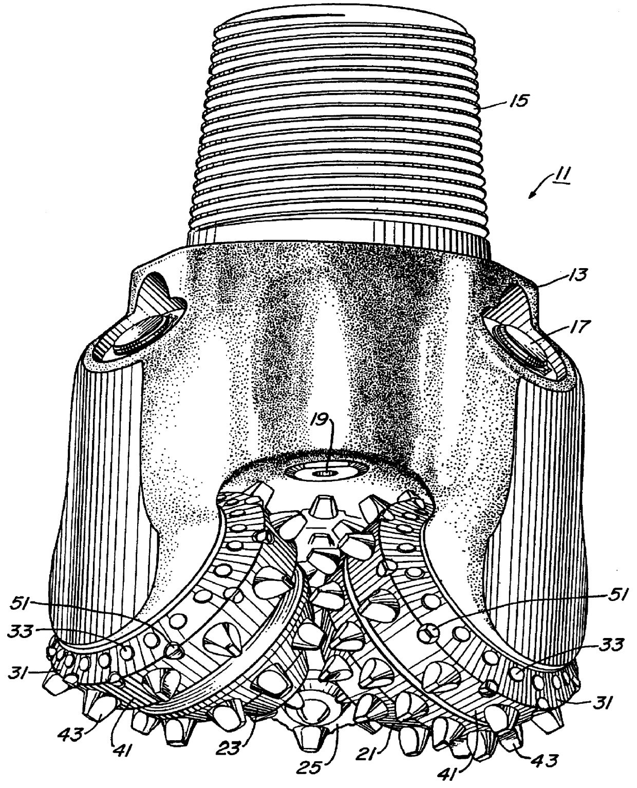
Referring now to the Figures and particularly to FIG. 1, an earth-boring bit 11 according to the present invention is illustrated. Bit 11 includes a bit body 13, which is threaded at its upper extent 15 for connection into a drill string. Each leg or section of bit 11 is provided with a lubricant compensator 17. At least one nozzle 19 is provided in bit body 13 to spray drilling fluid from within the drillstring to cool and lubricate bit 11 during drilling operation. Three cutters 21, 23, 25 are rotatably secured to a bearing shaft associated with each leg of bit body 13.

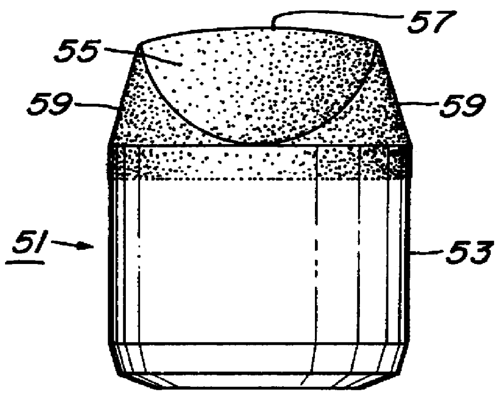
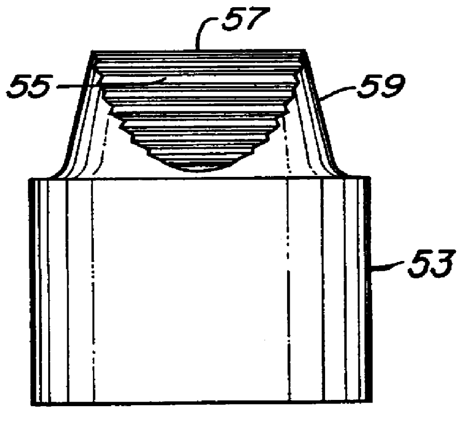
Each cutter 21, 23, 25 has a cutter shell surface including a gage surface 31 and a heel surface 41. Each cutter 21, 23, 25 provides a cutter element support for cutting elements. A plurality of cutting elements are arranged in generally circumferential rows on the cutter shell surface. Cutting elements preferably are secured in apertures in the cutters by interference fit and include gage cutting elements 33 on gag...


PUM


Abstract

An earth-boring bit has a bit body and at least one cantilevered bearing shaft depending inwardly and downwardly from the bit body. A cutter is mounted for rotation on the bearing shaft and includes a plurality of cutting elements. At least one of the cutting elements has a generally cylindrical body formed of hard metal with a convex cutting end. A plurality of recesses extend longitudinally from the apex to the junction. The recesses are shallow grooves symmetrically spaced about the axis. A layer of super-hard material is formed on the cutting end of the body and overlays the recesses formed thereon.

Description

TECHNICAL FIELDThe present invention relates to improvements in the cutting structure of earth-boring bits. More specifically, the present invention relates to bits having improved super-hard or diamond cutting elements.BACKGROUND ARTThe success of rotary drilling enabled the discovery of deep oil and gas reservoirs. The rotary rock bit was an important invention that made rotary drilling economical.Only soft earthen formations could be penetrated commercially with the earlier drag bit, but the two-cone rock bit, invented by Howard R. Hughes, U.S. Pat. No. 930,759, drilled the hard caprock at the Spindletop Field near Beaumont, Tex., with relative ease. That venerable invention, within the first decade of this century, could drill a scant fraction of the depth and speed of the modern rotary rock bit. If the original Hughes bit drilled for hours, the modern bit drills for days. Modern bits sometimes drill for thousands of feet instead of merely a few feet. Many advances have contribu...

Claims


Application Information

Patent Timeline
Patent Type & Authority Patents(United States)
IPC IPC(8): E21B10/46E21B10/16E21B10/52E21B10/56E21B10/567
CPCE21B10/16E21B10/5673E21B10/52
Inventor SCOTT, DANNY E.
Owner BAKER HUGHES INC
Why Eureka
Try Eureka