Hemostasis valve

a technology of hemostasis valve and catheter, which is applied in the field of hemostasis valve, can solve the problems of inability to obtain adequate sealing around the catheter wall, difficulty in obtaining a single hemostasis valve, and difficulty in obtaining a single catheter of wide varying diameter, and achieve the effect of convenient insertion

Inactive Publication Date: 2000-11-07
ST JUDE MEDICAL ATRIAL FIBRILLATION DIV
View PDF29 Cites 129 Cited by
  • Summary
  • Abstract
  • Description
  • Claims
  • Application Information

AI Technical Summary

Benefits of technology

The present invention involves a hemostasis valve housing unit which in one embodiment includes a longitudinally extended housing having first and second opposing open ends; a cap enclosing the first end and having an opening to permit insertion of a dilator or catheter into the longitudinally extended housing; and a valve located within the central passage of the longitudinally extended housing. The valve is provided with a sealing neck and sealing exit lips arranged so that a catheter may be readily inserted through the sealing neck and out the sealing exit lips. The sealing neck is elongated with a passageway passing therethrough. The sealing neck passageway contains narrowed and broadened portions where the diameter of the narrowed portion of the opening is smaller than the diameter of the broadened portion of the opening. The sealing neck is preferably supported by support shoulders which support the valve during the insertion of catheters or guidewires through the valve and on their withdrawal. The second end of the valve housing is attached to a sheath which is inserted into the vasculature.

Problems solved by technology

Because adequate sealing around the catheter walls cannot be obtained for a variety of catheters having varying diameters using conventional hemostasis valves, it has not been possible to employ a single hemostasis valve with catheters of widely varying diameters.
These problems are particularly acute when the guidewire technique is used.
Therefore, in the prior art it has been difficult to design a single hemostasis valve which will seal around both relatively large diameter catheters as well as relatively small diameter guidewires.
However, when guidewires or catheters which are too small in diameter are inserted into this hemostasis valve, the sealing advantages of the first, donut-shaped gasket are no longer available because the larger diameter donut hole will not seal around the smaller diameter guidewire or catheter.
Moreover, when catheters are employed having diameters which are extremely large in relation to the diameter of the hole in the donut-shaped gasket, the gasket may become separated from the hemostasis valve body or it may be unduly stretched so that it will not seal properly when a smaller sized catheter is inserted at a later time.
As in other prior art seals where two gaskets are utilized to form the seal, the device described in the '519 patent suffers the same deficiencies because its donut-shaped gasket can only accept catheters having a limited range of diameter sizes.
Moreover, this device is particularly susceptible to leakage when only a guidewire is in place.
However, this cannula, like the other prior art cannulas, suffers from a lack of universality and from poor sealing.
While two seals are employed, the second seal may only be used with catheters having a limited range of diameters and will provide little or no sealing for a guidewire.
However, it is extremely difficult to use this valve when relatively large diameter catheters are employed because the second seal is required to expand against the sidewalls of the cannula, thereby significantly increasing friction during insertion and the risk of hemodynamic dampening.
Moreover, the sealing means of the device described in the '229 patent is formed from two separate pieces thereby increasing the difficulties of manufacture and the likelihood that one of the seals may become dislodged particularly during use with large sized catheters.
Another problem shown by many prior art hemostasis cannulas is that the cardiologist must be able to "feel" the catheter as it is inserted through the gaskets or other sealing members of the hemostasis valve and ultimately into a blood vessel.
If insertion of the catheter through the hemostasis valve is too difficult, the cannula unit may be rejected by cardiologists as being difficult to use during catheter insertion.
Concomitantly, the use of hemostasis valves which exert undue pressure on the side walls of inserted catheters may lead to excessive hemodynamic dampening of the catheter.
In other words, excessive pressure on the exterior side-walls of a catheter may cause a narrowing of the catheter's diameter, thereby altering measurement parameters within the catheter.
In addition, hemostasis valves have also experienced problems from collapse of a portion or portions of the valve during the withdrawal of the dilator and the insertion of the catheter.
Further, repeated insertion and withdrawal of catheters and catheter related devices through conventional hemostasis valves has become more and more difficult.
This increase in force which is necessary for insertion and withdrawal further reduces the usability of conventional hemostasis valves.

Method used


Image

  • Hemostasis valve
  • Hemostasis valve
  • Hemostasis valve

Examples


second embodiment

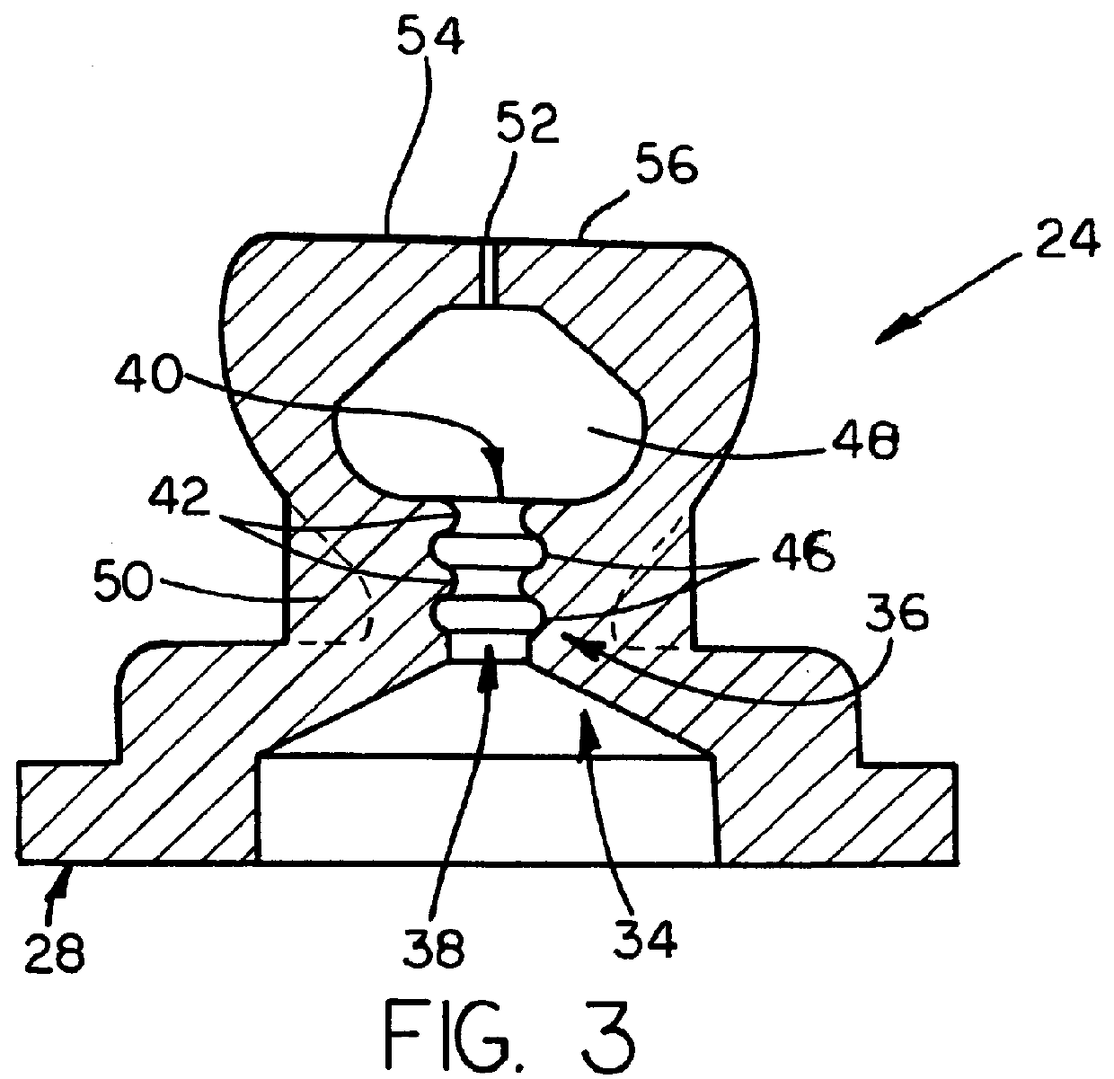
the seal is shown in FIG. 3. In this embodiment instead of two narrowed portions and a single broadened portion, three narrowed portions (42) and two broadened portions (46) are present with a broadened portion (46) placed between a pair of adjacent narrowed portions (42). The diameter of the narrowed (42) and broadened portions (46) of this second embodiment may be the same or different from the diameter of the narrowed and broadened portions of the first embodiment, with an enhanced "feel" resulting. Further, the diameter of narrowed portions 42 or broadened portions 46 may all be the same, or portions 42,44 may vary in sizes, some being larger or smaller in diameter.

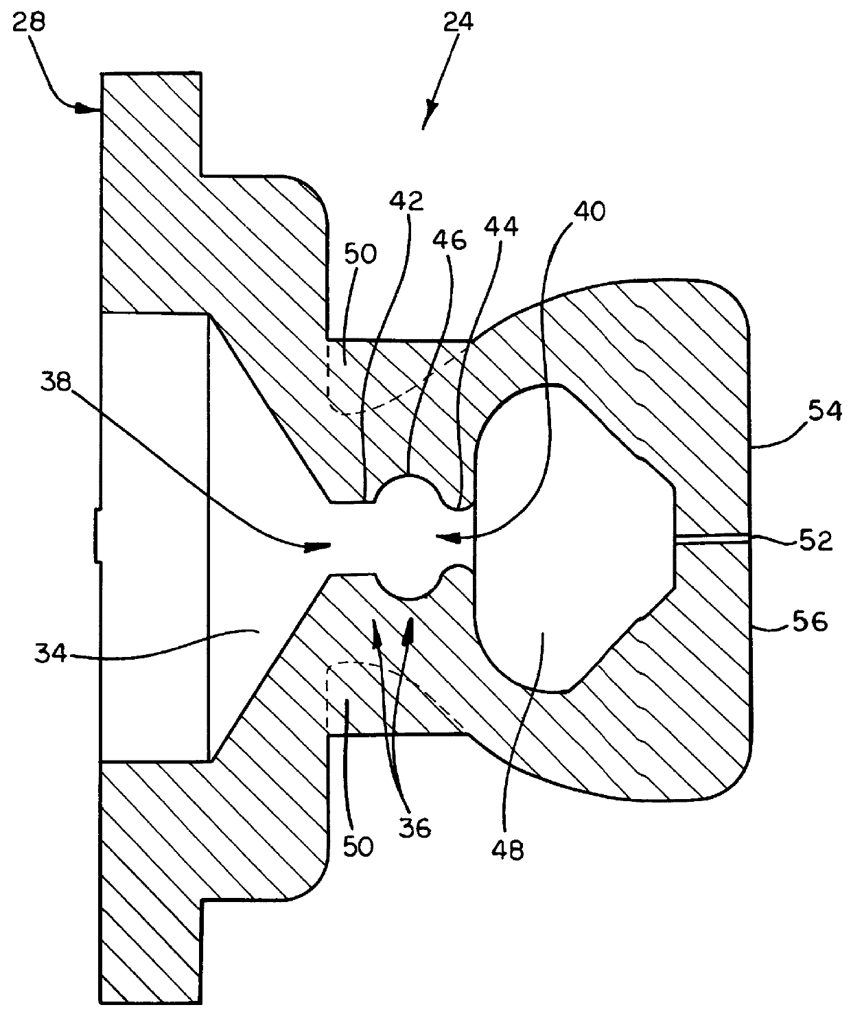
In a third embodiment as shown in FIG. 4, a single narrowed portion (42) and a single broadened portion (46) are present, wherein the single broadened portion (46) is preferably in communication with the conical receiving area (34). The diameter of the narrowed portion (42) is less than the diameter of a conventional ...


PUM


Abstract

A one-piece hemostasis valve located within a longitudinally extended housing, with the valve comprising an extended sealing neck having a passageway therethrough, communicating with a sealing chamber having opposing sealing exit lips and preferably support shoulders on the outside of the valve adjacent to the sealing neck to provide support for the valve. The passageway of the extended sealing neck contains narrowed and broadened portions to prevent blood loss when receiving a guidewire and catheter inserted through the passageway of the sealing neck.

Description

This invention relates to hemostasis valves. More particularly, this invention relates to an improved hemostasis valve containing a receiving area, a sealing chamber, sealing exit lips and a sealing neck between the receiving area and the sealing chamber, wherein the sealing neck contains broadened and narrowed portions which permit the introduction of different sized guidewires and catheters to pass through the valve with reduced resistance during passage.BACKGROUND OF INVENTIONThe introduction of catheters into blood vessels for a variety of purposes such as coronary angiography has been known for many years. Several techniques for introducing these catheters are available. One such technique is the cut-down method. Another is the Seldinger technique. This technique involves surgically opening a vein or artery with a needle, inserting a guidewire into the vein or artery through the lumen of the needle, withdrawing the needle, inserting over the guidewire a dilator located inside a...

Claims


Application Information

Patent Timeline
Patent Type & Authority Patents(United States)
IPC IPC(8): A61M39/02A61M39/06
CPCA61M39/0606A61M2039/0686A61M2039/0646A61M2039/0633
Inventor HECK, ALICIA F.KRUEGER, MARK D.
Owner ST JUDE MEDICAL ATRIAL FIBRILLATION DIV
Why Eureka
Try Eureka