Pneumatic transfer apparatus

a technology of pneumatic transfer and cylinder, which is applied in the direction of conveyors, instruments, atm details, etc., can solve the problems of large carriers through transfer conduits of significant distance, large blowers, and more complex service providers and customer stations than is mechanically and economically feasible, and achieves the effects of reducing the risk of malfunction, reducing the risk of failure, and rapid development of differential pressur

Inactive Publication Date: 2000-11-14
DIEBOLD NIXDORF
View PDF8 Cites 60 Cited by
  • Summary
  • Abstract
  • Description
  • Claims
  • Application Information

AI Technical Summary

Benefits of technology

It is a further object of the present invention to provide a pneumatic transfer apparatus for transporting items which transports items rapidly and which minimizes the risk of damage during transport.
It is a further object of the present invention to provide a pneumatic transfer apparatus which includes a carrier which provides more ready access to its interior area.
It is a further object of the present invention to provide a pneumatic transfer apparatus which includes a carrier which is enclosed to secure items therein during transport and which is readily accessed by a customer or a service provider.
It is a further object of the present invention to provide a pneumatic transfer apparatus for transporting items which is reliable and economical.
The system further operates in response to receipt of a command to transfer the carrier to the other of the service provider or customer station. The actuating mechanism operates to close the carrier to secure items therein before a differential pressure is produced in the transfer conduit to transfer the carrier towards the other station. This minimizes the risk of a malfunction. The service provider and customer station further include controlled sealing devices for controlling the release of pressure and the speed of the carrier as it arrives at the station . The controlled sealing devices also enable the rapid development of differential pressure when the carrier is desired to be moved away from the station. The actuating mechanism in each station includes a shock absorbing mounting to minimize wear due to repeated engagement with the carrier.

Problems solved by technology

The movement of substantially larger carriers through transfer conduits of significant distance generally requires much larger blowers and more complex service provider and customer stations than is mechanically and economically feasible.
This is desirable because the orientation of the carrier in such systems cannot be controlled.
This can cause the carrier to open during transport.
This may result in loss of the contents of the carrier.
The carrier may also become stuck in the tube disabling the system.
Loose items within the tube may also cause damage to the accelerator rings, which are seals which extend between the carrier and the inside wall of the tube.
If such a carrier is not properly closed and / or it opens in the tube during travel the carrier may become jammed in the tube.
Freeing a jammed carrier may be time consuming and costly.
Customers are inconvenienced until the system is fixed.
The customer whose material is held in the jammed carrier is particularly inconvenienced.
However, the weight and physical size associated with the transport of relatively large quantities of medical items (which quantities are usually the most cost effective to purchase) makes conventional pneumatic tube systems unsuitable for this use.
In addition, most persons would find it difficult to manipulate the carriers due to the larger size and weight.

Method used


Image

  • Pneumatic transfer apparatus
  • Pneumatic transfer apparatus
  • Pneumatic transfer apparatus

Examples


Embodiment Construction

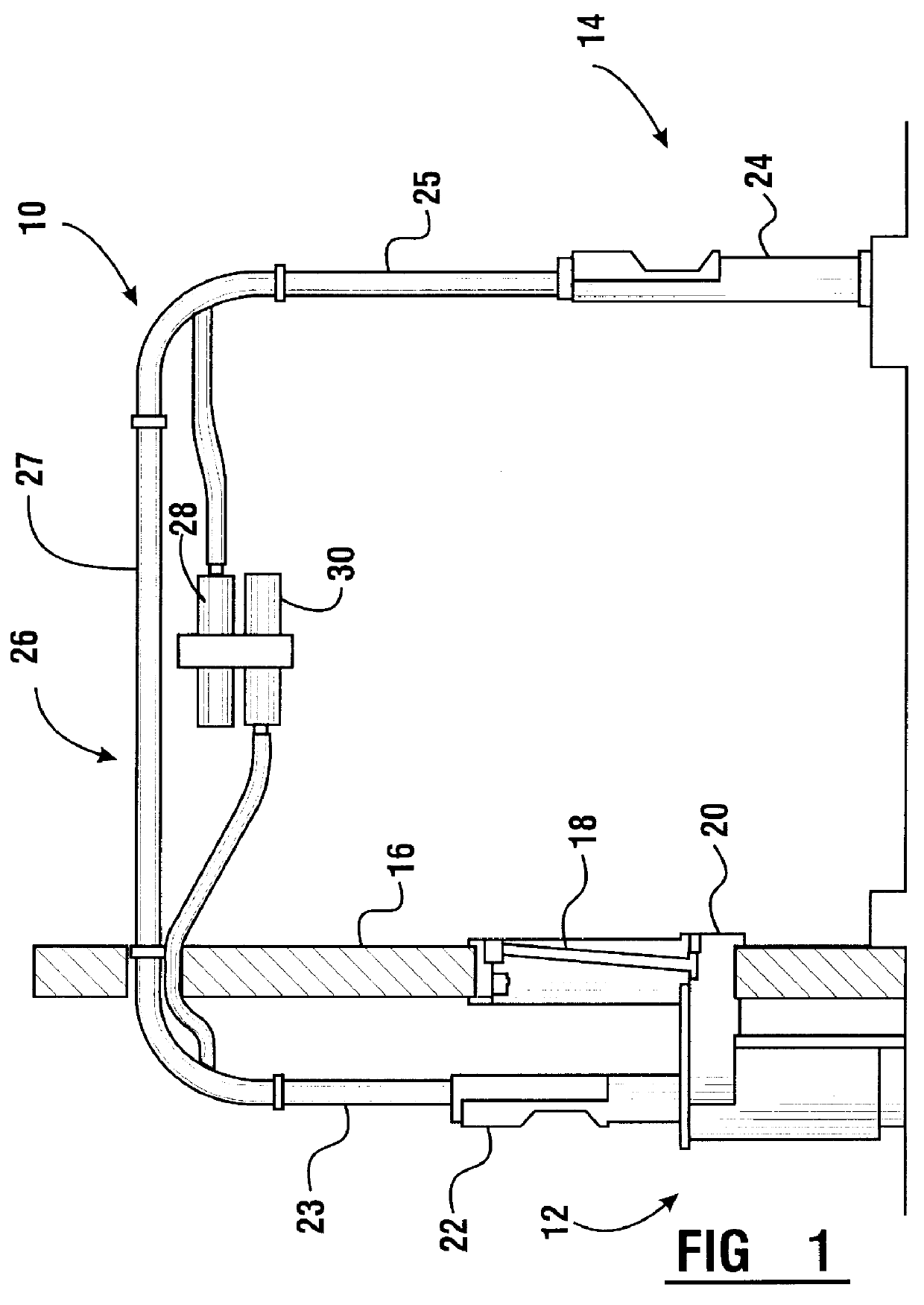
Referring now to the drawings and particularly to FIG. 1, there is shown therein one preferred embodiment of the pneumatic transfer apparatus of the present invention generally indicated 10. The system 10 includes a service provider station 12 and a customer station 14. In the embodiment of the invention shown, the service provider station 12 is preferably operated by a pharmacist, cashier, or other personnel in a drug store, pharmacy or similar establishment. The customer station in the preferred embodiment is at a drive through or walk up location located outside the facility in which the pharmacy is operated. Of course, the present invention may be used in many other transaction environments as well, such as in banking, gaming, ticketing, vending and other sales or service facilities.

System 10 is installed through a building wall 16, which in the embodiment shown is an exterior building wall of a drugstore or other building which houses a pharmacy. Wall 16 has installed therein a...


PUM


Abstract

A pneumatic transfer apparatus (10) includes a service provider terminal (22) and a customer terminal (24). A carrier (32) is moved through a transfer conduit (26) between the customer and service provider terminals by a differential pressure generating mechanism (28, 30). Each of the customer and service provider terminals includes an actuator mechanism (54, 82). The actuator mechanism is operative to orient an opening in the housing of the carrier with a transfer opening in the transfer conduit. The actuator mechanism is further operative to move an inner shell (100) relative to an outer shell (96) of the carrier so as to bring openings in said inner and outer shells into alignment which enables accessing the interior area of the carrier.

Description

This invention relates to devices and systems for transporting items from one location to another. Specifically, this invention relates to a pneumatic transfer apparatus and system which are used for transporting items such as medications and related articles such as prescriptions and payments, between a service provider station and a customer station.Systems which transport items between stations are known in the prior art. Some prior art transfer systems include systems in which items are moved between a service provider and a customer in a carrier that is moved through a transfer conduit. The carrier is moved through the transfer conduit by differential pressure that is selectively produced in areas of the conduit. The differential pressure is commonly produced by drawing a vacuum in the area into which the carrier is to be moved, or by producing a positive pressure in the area behind the carrier, or both. In either event the differential pressure between the areas in front and b...

Claims


Application Information

Patent Timeline
Patent Type & Authority Patents(United States)
IPC IPC(8): B65G51/34B65G51/00B65G51/26G07F19/00E05G7/00
CPCB65G51/26B65G51/34G07F19/205G07F19/20E05G7/008
Inventor GROMLEY, NEIL C.BECK, ROBERT J.KLATT, ROBERT J.BAKERINK, ALLAN R.GALLAGHER, LARRY R.MARMON, VINCENT T.
Owner DIEBOLD NIXDORF
Why Eureka
Try Eureka