Press machine

a press machine and slide technology, applied in forging presses, forging/pressing/hammering apparatuses, manufacturing tools, etc., can solve the problems of limited up and down slide motion and limited application range of press machines

Inactive Publication Date: 2000-11-21
YAMADA DOBBY
View PDF9 Cites 11 Cited by
  • Summary
  • Abstract
  • Description
  • Claims
  • Application Information

AI Technical Summary

Benefits of technology

The position adjusting mechanism may include a rotating body in the form of a circular plate, the rotating body being provided with a threaded hole and being disposed on the frame so as to rotate about an axis extending in the vertical or horizontal direction but to rotate neither in the vertical direction nor in the horizontal direction, a rotation mechanism for rotating the rotating body, and a moving body disposed on the frame so as to move in the vertical direction. This moving body is pivotally connected with the first pivot and has a male threaded portion capable of mating with the threaded hole. With the position adjusting mechanism, the position of the moving body can be finely adjusted in the vertical or horizontal direction, so that the stroke of the slide motion in the up and down directions can be finely adjusted.
However, the position adjusting mechanism or device may include a rotating body pivotally connected with the connection mechanism such that the pivotal joint to the connection mechanism may rotate about an axis extending in one direction, preferably about an axis in parallel with the axis of the joint of both levers, and a rotation mechanism for rotating the rotating body. In this way, the pivotal joint can be displaced as the rotating body is rotated by the rotation mechanism, thus enabling the stroke of the slide motion in the up and down directions to be finely adjusted.
Under the situation in which the link is pivotally connected with the joint of both levers or in its vicinity, and the slide is set on the position of the lower dead point, if the rotating body is angularly rotated by the driving mechanism, the rotating body is angularly rotated about the joint between both levers or the vicinity thereof, and the bent position and bent angle of both levers are changed. With this, the swinging position and swinging angle of the second crankshaft is changed as the first crankshaft is rotated. However, any change would be hardly caused with respect to not only the position of the joint between both levers but also the position of the lower dead point. As a result, it becomes possible not only to finely adjust the stroke of the slide motion in the up and down directions, but also to keep the position of the lower dead point almost unchanged even if the stroke is changed.
Contrary to the above, under the situation in which the link is connected with the connection mechanism at a point apart from the joint of both levers, if the rotating body is angularly rotated by the rotation mechanism, the rotating body is angularly rotated about a point apart from the joint of both levers, and the joint point between the rotating body and the connection mechanism is angularly moved in the same or opposite direction. As a result, it becomes possible not only to finely adjust the stroke of the slide motion in the up and down directions, but also to make the positional change of the lower dead point smaller even if the stroke is changed.
The first pivot of the one lever can be pivotally connected with the position adjusting device. With this, as the vertical or horizontal position of the first pivot can be directly adjusted by the position adjusting device, it becomes easier to adjust the vertical or horizontal position of the first pivot.

Problems solved by technology

In the prior art press machines of this kind, however, the stroke of a slide motion in the up and down directions is limited to a preset value determined depending on the sorts of press processings such as the precise press processing (low speed press processing), the stamping processing (high speed press processing) and so forth.
Consequently, in the prior art press machine of this kind, the stroke of the slide can not be changed, so that the applicable range of the press machine has been limited by such limited stroke of the slide.

Method used


Image

  • Press machine
  • Press machine
  • Press machine

Examples


Embodiment Construction

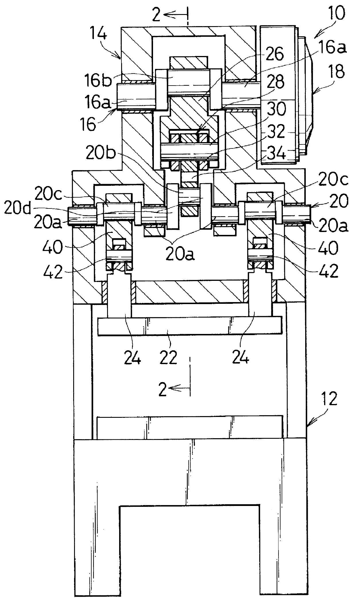
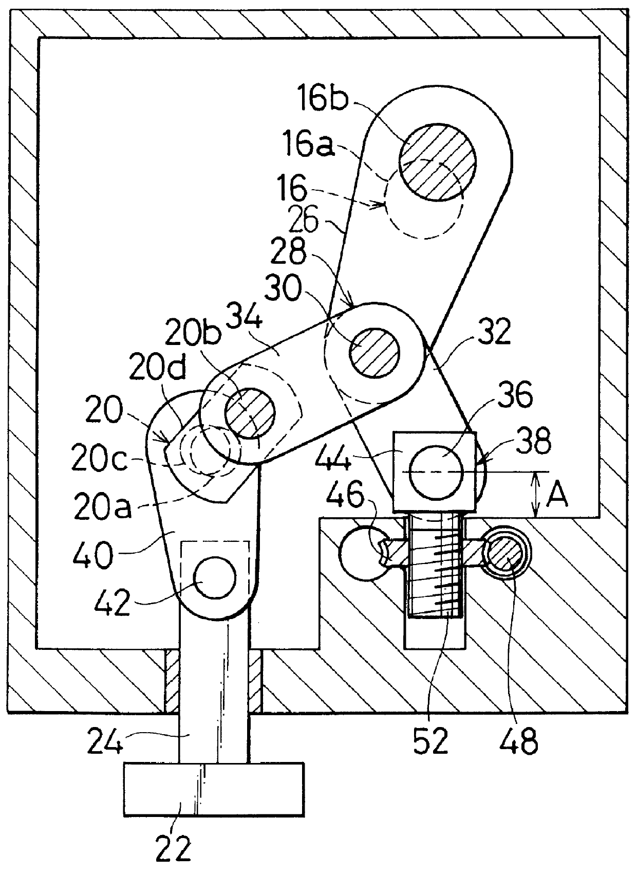
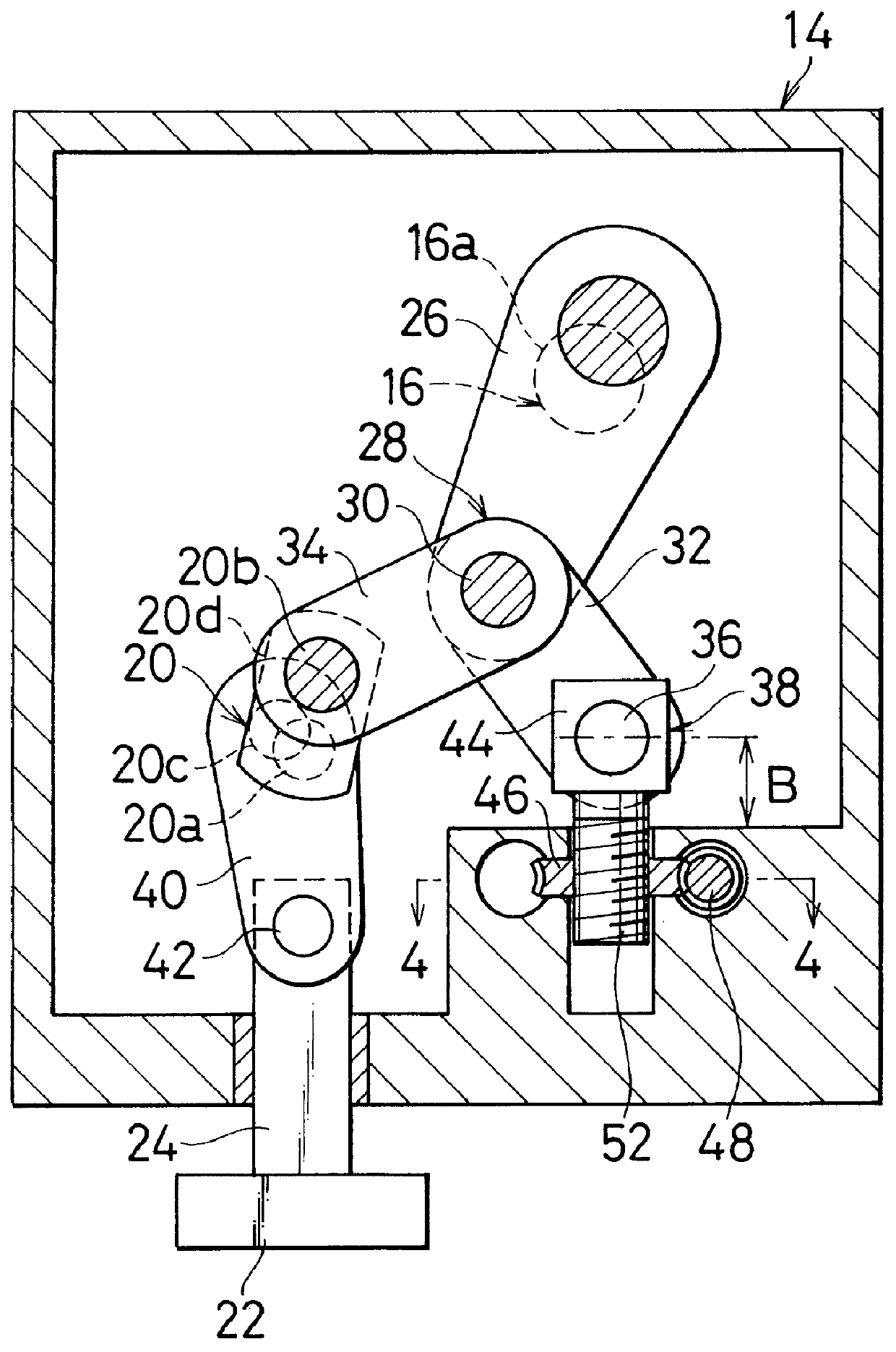
Referring now to FIGS. 1 through 4, a press machine 10 includes a lower frame 12 on which a lower die is mounted, and an upper frame 14 supported on the lower frame 12.

The first crankshaft 16 is supported by the upper frame 14 such that it can rotate about an axis extending through the upper frame 14 in the horizontal direction. The crankshaft 16 supports at its one end a flywheel 18 which is provided with a mechanism of deceleration. This crankshaft 16 also includes a plurality of principal shaft portions 16a which are supported by the frame 14, and an eccentric shaft portion 16b which is formed between two principal shaft portions 16a.

The second crankshaft 20 is arranged obliquely downward relative to the first crankshaft 16 so as to rotate about an axis extending through the upper frame 14 in the horizontal direction. The second crankshaft 20 includes a plurality of principal shaft portions 20a supported by the upper frame 14, a first eccentric shaft portion 20b located at the ce...


PUM

PropertyMeasurementUnit
bending angleaaaaaaaaaa
swinging angleaaaaaaaaaa
vertical heightaaaaaaaaaa

Abstract

A press machine includes a frame, a first crankshaft rotated by a driving source, a second crankshaft connected with a slide, and a connection mechanism provided with a pair of levers connected with each other so as to carry out their bending-stretching motion as the first crankshaft is rotated. One lever has a first pivot and is connected, through the first pivot, with a position adjusting device for adjusting the position of the first pivot in the vertical or horizontal direction. The other lever has a second pivot and is connected, through the second pivot, with the eccentric shaft portion of the second crankshaft. The slide is connected with other eccentric shaft portion of the second crankshaft.

Description

1. Field of the InventionThe present invention relates to a press machine of the class in which the first and second crankshafts are connected with each other by means of a connection mechanism including a pair of links.2. Prior ArtPress machines using a link mechanism such as a knuckle joint, a toggle joint and so forth, are already known to the public. For instance, an example of such is disclosed by the Japanese Patent Appln. Public Disclosure (KOKAI) No. 9-225686. This press machine includes a first crankshaft rotated by a driving source and a second crankshaft connected with a slide. These crankshafts are connected with each other by means of a connection mechanism using three of links.In the prior art press machines of this kind, however, the stroke of a slide motion in the up and down directions is limited to a preset value determined depending on the sorts of press processings such as the precise press processing (low speed press processing), the stamping processing (high sp...

Claims


Application Information

Patent Timeline
Patent Type & Authority Patents(United States)
IPC IPC(8): B30B15/00B30B1/26B30B15/06B30B1/14
CPCB30B1/263B30B15/0029B30B1/266
Inventor YOSHIDA, AKIHIRO
Owner YAMADA DOBBY
Why Eureka
Try Eureka