Apparatus for influencing a wing root airflow in an aircraft

a technology of aircraft wings and airflow, applied in the direction of wing adjustment, influencer by generating vortices, wings, etc., can solve the problems of increasing maintenance, increasing the weight, cost and complexity of the aircraft, and particularly the high lift system

Inactive Publication Date: 2000-11-28
DAIMLER CHRYSLER AEROSPACE AIRBUS
View PDF15 Cites 47 Cited by
  • Summary
  • Abstract
  • Description
  • Claims
  • Application Information

AI Technical Summary

Problems solved by technology

Such auxiliary flaps require additional drive mechanisms and linkages, and are therefore subject to possible malfunction and failure, and require increased maintenance, while also increasing the weight, cost and complexity of the aircraft, and particularly the high lift system.

Method used


Image

  • Apparatus for influencing a wing root airflow in an aircraft
  • Apparatus for influencing a wing root airflow in an aircraft
  • Apparatus for influencing a wing root airflow in an aircraft

Examples


Embodiment Construction

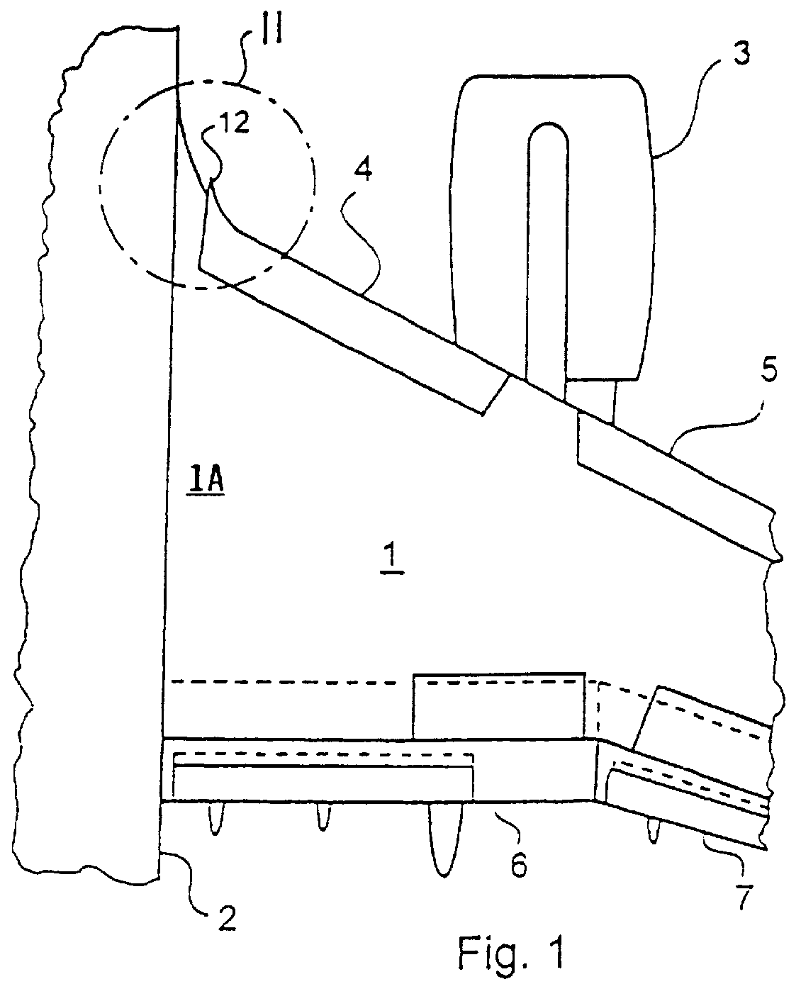
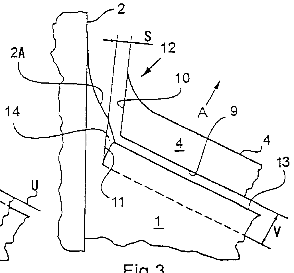
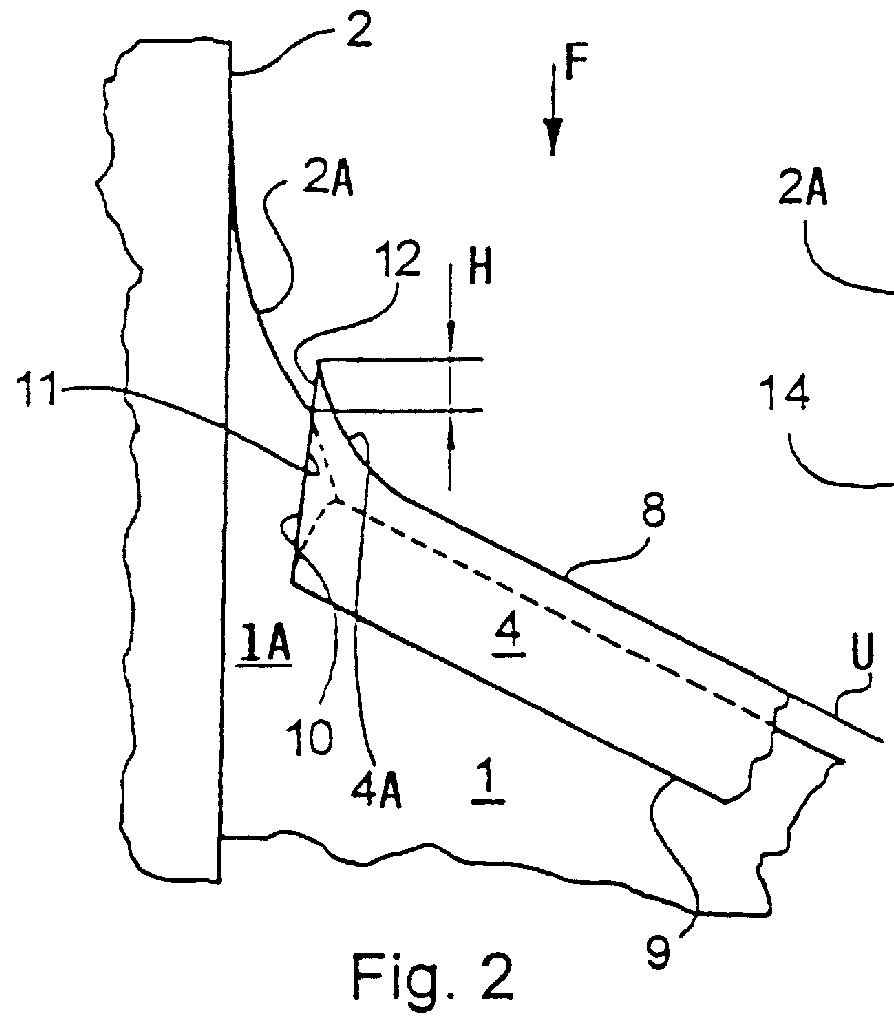
FIG. 1 shows a portion of an aircraft including a fuselage 2 and a main wing 1 connected to the fuselage 2 along a wing root 1A. A jet engine 3 is mounted on the wing 1. Particularly, FIG. 1 shows only the area of the transition between the wing root and the fuselage on the right side of the aircraft, but it should be understood that the same elements as illustrated form a matching pair on the left side of the aircraft which is not illustrated. The illustrated right main wing 1 is equipped with a high lift system including slats arranged on the leading edge, and right side landing flaps 6 and 7 arranged along the trailing edge. Particularly, the leading edge slats are divided into an inboard slat 4 and an outboard slat 5 due to the location of the engine 3 in the illustrated example embodiment. A vortex generator 12 is arranged on the inboard end of the slat 4, i.e. the end of the slat 4 closer to the fuselage 2. The vortex generator 12 may be fabricated from any known materials use...


PUM


Abstract

An apparatus advantageously influences the wing root airflow along the wing root of an aircraft having a high lift system including leading edge slats provided on the main wings. The apparatus includes a respective vortex generator arranged on the inboard end of each leading edge slat in the area of the wing root, and further includes a respective transition fairing arranged on a separation edge that is let into the leading edge of the wing root and that borders along the inboard edge of the respective slat. The vortex generator is a rigid member fixed to the leading edge slat and may be in the shape of a horn, a disk, or a winglet. The transition fairing may be a rigid member fixed to the wing root along the separation edge, or may be a flexible elastic member that can be inflated to have a variable outer contour. The present system avoids the need of additional independently movable auxiliary flaps, and thus achieves a reduced weight, complexity, and maintenance requirement.

Description

PRIORITY CLAIMThis application is based on and claims the priority under 35 U.S.C. .sctn.119 of German Patent Application 197 19 922.4, filed on May 13, 1997.The invention relates to an apparatus for influencing a wing root airflow over the root area of a wing in an aircraft equipped with a high lift system.BACKGROUND INFORMATIONHigh lift systems are necessary for achieving the lowest possible take-off and landing speeds for transport aircraft. Namely, such high lift systems provide the high lift, or particularly the increased lift, that is required during slow flight. Typically, such a high lift system comprises landing flaps and leading edge slats arranged on the main wing of the aircraft. In this context, it is generally also necessary to provide measures for ensuring that an undisturbed wing root airflow will flow over the upper surface of the wing without separating therefrom, especially in the area of the wing-fuselage transition, i.e. at the wing root. In order to achieve thi...

Claims


Application Information

Patent Timeline
Patent Type & Authority Patents(United States)
IPC IPC(8): B64C21/00B64C23/00B64C23/06B64C9/24B64C9/00
CPCB64C9/24B64C23/06Y02T50/44Y02T50/162Y02T50/10Y02T50/40
Inventor FLAIG, AXELSCHWETZLER, DETLEVSTACHE, DECEASED, ULRICH
Owner DAIMLER CHRYSLER AEROSPACE AIRBUS
Why Eureka
Try Eureka