Infrared eye movement measurement device

Inactive Publication Date: 2000-11-28
BERTEC +1
View PDF1 Cites 108 Cited by
  • Summary
  • Abstract
  • Description
  • Claims
  • Application Information

AI Technical Summary

Benefits of technology

The preferred embodiment of the device utilizes infrared measurement means. The infrared illuminators are attached to the horizontal component of the mounting means and oriented along the horizontal axis of the eye(s) in an approximately linear fashion. The sensors (e.g. photo detectors) are located above and below the illuminators. Therefore, the full range of horizontal and vertical eye movement can be measured with minimal inconvenience to the application and minimal view obstruction.
A head

Problems solved by technology

Regarding eye movement measurement devices, the prior art required precise adjustments for each subject, and complete to partial blocking of the subject's visual range which detrimentally inhibited testing capabilities.
Certain devices limited the subject's mobility by requiring the subject to remain perfectly still during measurement.
Limbus trackers are usually cheap and easy to use but generally these are only useful for measurements in one axis at a time, that is, they are not gaze monitors.
The disad

Method used


Image

  • Infrared eye movement measurement device
  • Infrared eye movement measurement device
  • Infrared eye movement measurement device

Examples


Example

The invention disclosed herein relates to an eye movement measurement device which utilizes infrared technology to measure horizontal and vertical eye movement, capable of measuring each eye independently or both eyes jointly, and measuring horizontal and vertical movements separately or jointly.

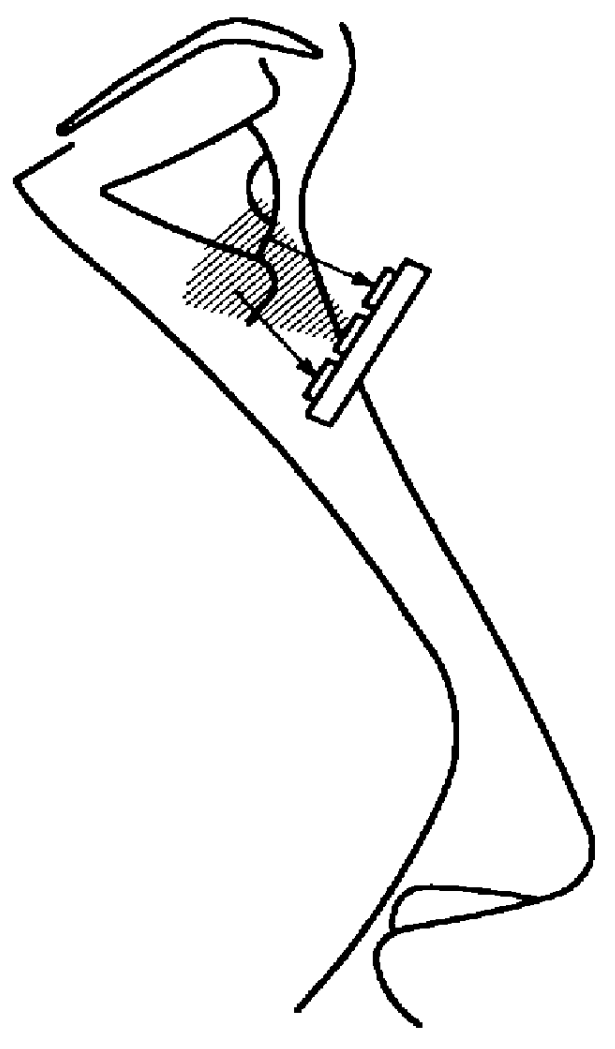
The device is comprised of a nose bridge and mounting means. The nose bridge is similar in design to that used on ordinary eye glasses and rests on the user's nose. The mounting means are attached to the nose bridge and house the measuring and calculation technology.

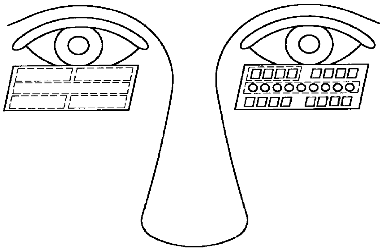
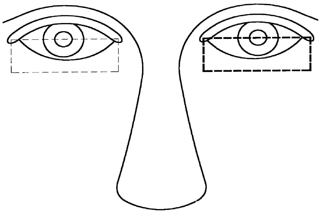
The measuring technology of the preferred embodiment is comprised of infrared illuminators and sensors (e.g., photo detectors) FIGS. 1A and 1B mounted on a light weight horizontal component FIGS. 1A and 1B. The illuminators and sensors are aligned in an approximately linear fashion FIG. 1A to provide for maximum measurement range of horizontal and vertical eye movement FIGS. 2, 3A-C, and 4A-C. The horizontal component is attached...


PUM


Abstract

Disclosed herein is a device for measuring horizontal and vertical eye movement utilizing infrared technology. The device rests on the user's nose and, in alternate versions, can be secured to the user's head via a head strap or temple arms which will provide greater alignment and applications. It is comprised of a nose bridge piece and mounting means which house the calculation and measurement technology. The nose bridge is similar to that of ordinary eye glasses with the mounting means, or head strap, or temple arms attached thereto. The mounting means consist of a lightweight horizontal component which extends from the nose bridge and underneath the eyes. This component is located below the horizontal center of the eye and rests above the cheek area of the user's face. Illuminators, which are oriented approximately linear to the horizontal axis of the eye on the component, radiate light into the lower portion of the eye. Sensors, which are above and below the illuminators on the component, detect and measure the amount of reflected light. The device is capable of measuring both axes independently and jointly, as well as both eyes independently and jointly. Utilizing a robust algorithm, accurate adjustment and alignment are not required. The device itself does not require adjustment or alignment, only adjustments for the user's facial features are needed. Therefore, this device only obstructs the bottom portion of the user's lower field of view, leaving the forward, side-to-side, and upward fields completely unobstructed, as well as requires only minimal adjustment and alignment. Thus, it has advantages, applications, and usefulness not contemplated by the prior art.

Description

The presently disclosed device relates to the measurement of eye movement. Regarding eye movement measurement devices, the prior art required precise adjustments for each subject, and complete to partial blocking of the subject's visual range which detrimentally inhibited testing capabilities. Certain devices limited the subject's mobility by requiring the subject to remain perfectly still during measurement. These prior devices were designed to be worn as goggles, helmets, or spectacles which housed the measurement technology.The main types of eye movement measurement and monitoring systems in common use are: Infrared; Video; Electro-oculography; Limbus trackers; Purkinje reflection trackers, and Scleral Coil trackers. Limbus trackers are usually cheap and easy to use but generally these are only useful for measurements in one axis at a time, that is, they are not gaze monitors. For accurately assessing point of gaze the most common method is the video tracker, where the pupil or i...

Claims


Application Information

Patent Timeline
IPC IPC(8): A61B3/113
CPCA61B3/113G06V40/19
Inventor OBER, JAN KRZYSZTOFOBER, JAN JAKUB
Owner BERTEC
Why Eureka
Try Eureka