Simplified 3D Viewer

Inactive Publication Date: 2004-09-16
LO ANTHONY
View PDF2 Cites 5 Cited by
  • Summary
  • Abstract
  • Description
  • Claims
  • Application Information

AI Technical Summary

Benefits of technology

[0015] When this stereographic viewer is held with its aperture panel at an appropriate distance from a reflection print, light rays from the left hand image are directed through the let hand lens to the left eye and light rays from the right hand image are directed through the right hand lens to the right eye. This creates the effect of a single, merged stereo image.
[0017] The configuration of the six walls allows the viewer to be erected when used and folded flat for convenient storage and transportation.
[0018] The toggle tabs joined to the left and right edges of the top and bottom panels serve form a seal that prevents stray light from entering the viewing chamber.
[0034] Lenses 8 & 9 mounted on a concave panel 7 reflect stray light away from the eyes. By eliminating the hood 3, which must be big enough to accommodate eyeglasses, the design is simplified, and the viewer is far less bulky. It offers the additional advantage that the viewer no longer needs to touch the observer's face, which could be embarrassing for people wearing heavy make-up.

Problems solved by technology

However, it is heavy, rigid, complicated to fabricate and inconvenient to store and transport.
It is not easily collapsible.
The prior art box style stereographic viewer for transparencies has the disadvantage that changing stereographic transparencies for viewing is inconvenient.
The prior art box style stereographic viewer for transparencies has the disadvantage that preparing and changing stereographic reflection prints for viewing is inconvenient.
In practice it is very difficult to construct such a viewing chamber, make it both collapsible and erectable, and block out the stray light entering the viewing chamber.
The prior art box style stereographic viewers have a collapsible and erectable viewing chamber, but they do not have a mechanism to conveniently secure the chamber in its erected position, which at the same time can be easily disengaged when the viewing chamber needs to be collapsed.

Method used


Image

  • Simplified 3D Viewer
  • Simplified 3D Viewer
  • Simplified 3D Viewer

Examples


Embodiment Construction

by an Example:

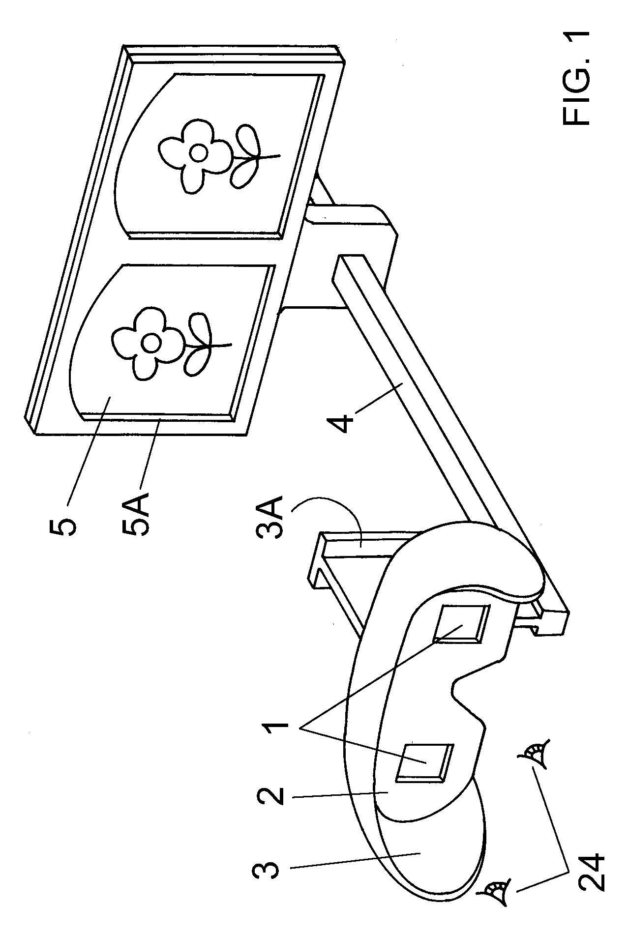
[0039] The invention is described by an example made of paper.

[0040] In practice, other foldable, ductile materials can be used.

[0041] Several refinements are described afterwards.

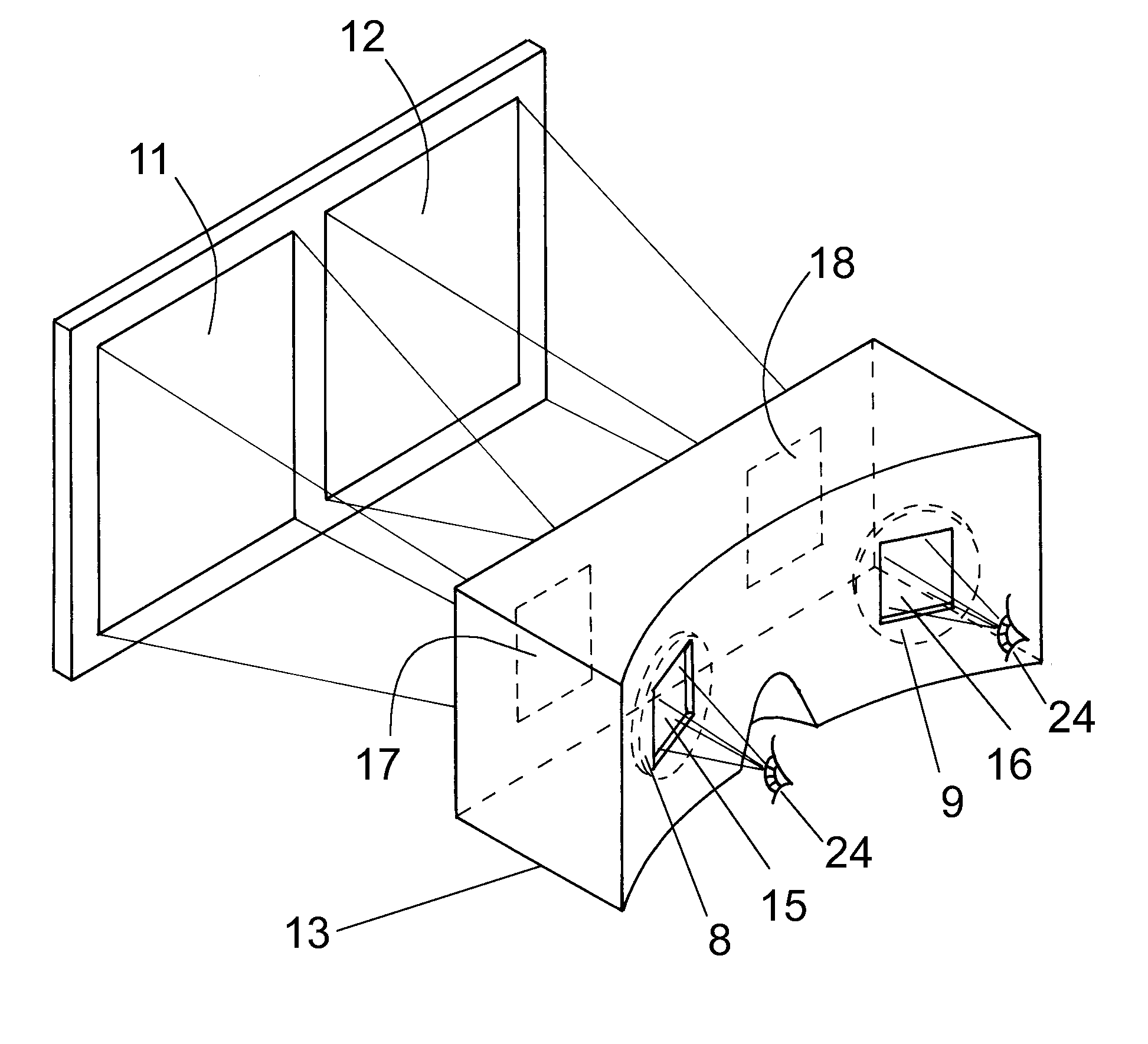
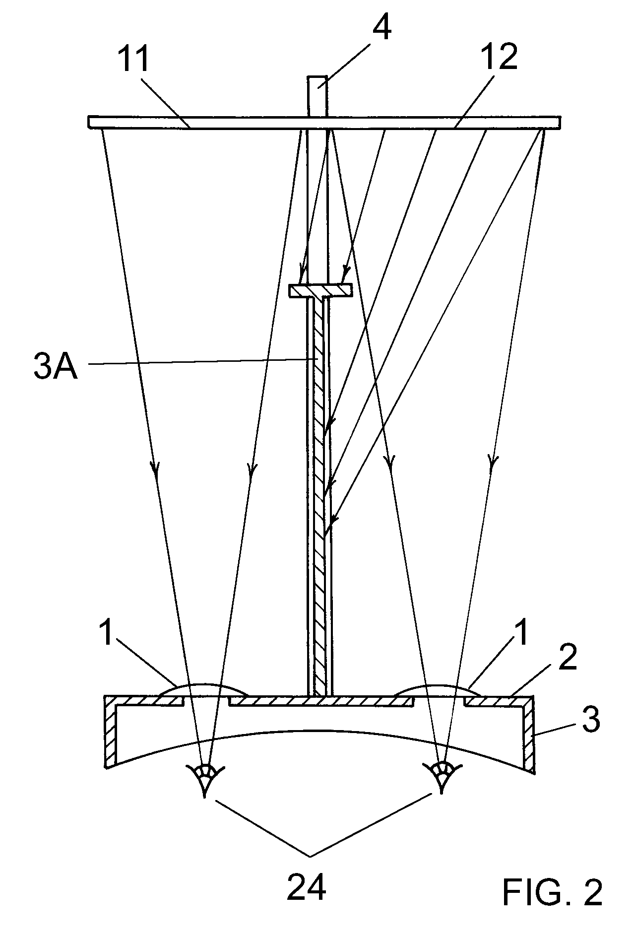
[0042] FIG. 5 shows the invention together with a pair of mounted 3D images and the user's eyes 24 in top sectional view. A pair of suitably mounted 3D images comprising the left hand image 11 and the right hand image 12 is held at a distance from the pair of objective lenses 8 & 9 so that the left eye is presented with a virtual image of the left image 11 focused at the about 2 meters in front of the left objective lens and the right eye is presented with a virtual image of the right image 12 also focused at about 2 meters in front of the right object lens.

[0043] An opaque box 14 with two pairs of openings on opposite panels is introduced in such a manner so that the pair of objective lenses 8 and 9 can be mounted over the pair of holes 15 and 16 so that the pitch between the centers of the ...


PUM


Abstract

A foldable viewer having a collapsed state and an erected state. The viewer includes a collapsible and erectable viewing chamber, a viewing panel having a pair of lenses, an aperture panel having a pair of apertures, and a septum set into the aperture panel. The viewing chamber comprises front, rear, top and bottom planar walls which are contiguously joined, left and right walls joined to the front and rear walls but not joined to the top and bottom walls, and toggle tabs joined to the left and right edges of the top and bottom panels.

Description

[0001] This application claims priority rights under 35 U.S.C. .sctn. 119(e)(1) based on provisional U.K. Patent Application GB 0304728.9 filed on 1st Mar. 2003.BACKGROUND OF INVENTION[0002] The present invention relates to a stereographic viewer for viewing stereo photographs, also known as reflection prints.[0003] The popularity of three-dimensional, or stereo, photographs is increasing along with technology advances in the field. Stereo photographs are created by projecting dual images of the same subject adjacent to each other on the same exposure of film. The dual images are known as a left and right stereo pair. This stereo pair can be viewed with three-dimensional, or stereo, effect, through an appropriate stereographic viewer.[0004] The typical stereographic viewer achieves its purpose by directing light rays from the left hand image to the left eye and light rays from the right hand image to the right eye to create the effect of a single, merged stereo image. Ideally, the l...

Claims


Application Information

Patent Timeline
IPC IPC(8): G02B27/22H04N15/00
CPCG02B27/2228G02B30/34
Inventor LO, ANTHONY
Owner LO ANTHONY
Why Eureka
Try Eureka