Crankshaft thrust face burnisher and method

a crankshaft and thrust face technology, applied in grinding machines, grinding/polishing apparatuses, manufacturing tools, etc., can solve the problems of simultaneous burnishing of the opposing thrust face, the crapping of such crankshafts for recycling, and the centering of the tool, so as to achieve free radial burnishing

Inactive Publication Date: 2000-12-05
HEGENSCHEIDT MFD
View PDF12 Cites 12 Cited by
  • Summary
  • Abstract
  • Description
  • Claims
  • Application Information

AI Technical Summary

Benefits of technology

One of the features, objects and advantages of this invention is to provide a new and improved burnisher apparatus which incorporate spring units which allow the burnishing to

Problems solved by technology

Such distortion of the thrust faces results in crankshaft rejection causing scrapping of such crankshafts for recycling.
With such a spring biased workpiece positioning arrangement, the relative movement between the tool and thrust faces results in the centering of the tool between the thrust faces and the simultaneous burnishing of the opposing thrust faces.
However, manufacturing situations arise in which it is not desirable or not possible to allow such lateral or axial movement of the crankshaft.
This can also occur when the crankshaft thrust faces become damaged during the manufacturing proces

Method used


Image

  • Crankshaft thrust face burnisher and method
  • Crankshaft thrust face burnisher and method
  • Crankshaft thrust face burnisher and method

Examples


Embodiment Construction

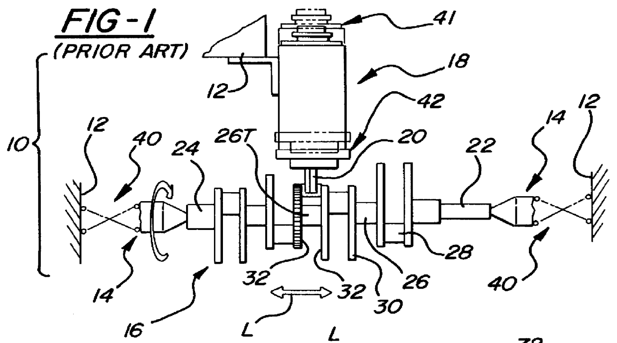
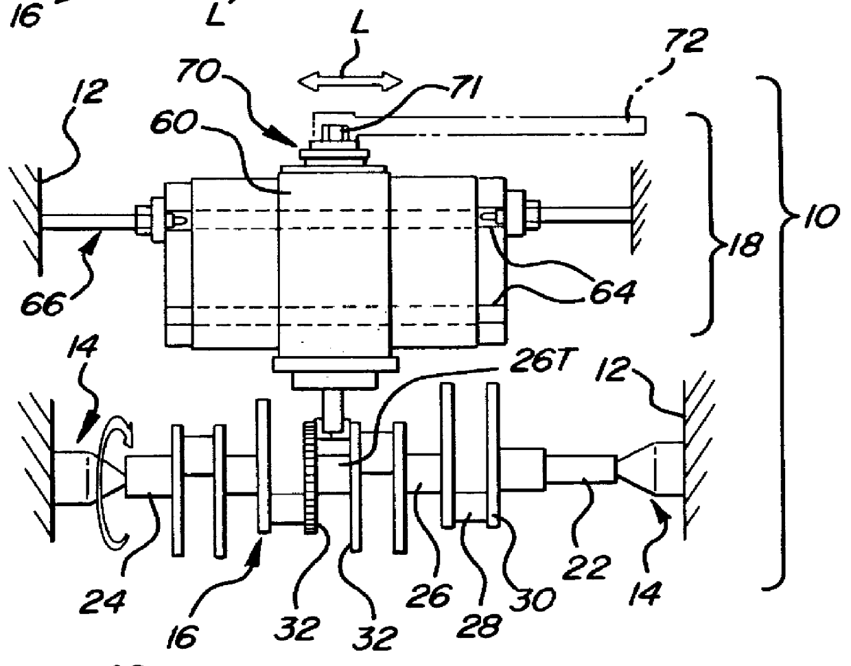
A portion of the prior art production crankshaft burnishing machine is shown generally at 10 in FIG. 1. The burnishing machine includes a frame 12, workpiece holders 14 for holding a crankshaft 16, and a burnishing assembly 18. In addition, the burnishing machine 10 may also include a cutting tool assembly (not shown) for machining surfaces of a crankshaft or other machining or metal working operations. However, the present invention relates to a machine and operation in which surfaces of the workpiece are burnished or mechanically worked to reduce roughness and provide a highly finished surface as will be discussed.

Turning now to the workpiece, the crankshaft includes a nose 22, an opposing end 24, a plurality of main 26 and pin journals 28, and counterweights 30 disposed between the main 26 and pin journals 28. In an engine assembly (not shown), the main journals 26 of the crankshaft 16 are retained in corresponding main bearings (not shown) in an engine block. One crankshaft main...


PUM

PropertyMeasurementUnit
Forceaaaaaaaaaa
Torqueaaaaaaaaaa

Abstract

A burnisher for use with a lathe or production machine to burnish opposing thrust faces of a crankshaft laterally fixed and rotatably driven thereby. The tool of the burnisher has a plurality of opposing burnishing rollers that operatively engage under opposing torsional load thrust faces of the crankshaft rotatably driven by the lathe or production machine. The burnisher features biasing spring construction that provides for the movement of the burnishing tool laterally into a centered working position relative to the opposing surfaces of the crankshaft when sufficient turning force or torque is applied to the burnishing tool. This construction provides for even application of burnishing force by the burnishing rollers onto the thrust faces for application in which the workpiece is fixed laterally without becoming distorted.

Description

The present invention relates to burnishing tools for surface finishing plastically deformable metal parts. More specifically, the invention relates to a new and improved burnishing tool adapted to plastically work and finish the thrust walls of an internal combustion engine crankshaft so that they are free from distortion and have improved surface finish quality and service life.In an engine, parallel and spaced apart thrust faces of a crankshaft act to axially locate the crankshaft within an engine block. During vehicle operation, in which many transmission upshifts and downshifts are made and in which the engine crankshaft can rotate at relatively high speeds, the thrust faces thereof come into contact with the thrust face bearings of the engine block. The frictional contact requires the thrust faces to have very smooth surfaces free from distortion, or runout, for smooth operation and for optimizing wear characteristics between these parts.Prior to the present invention, burnish...

Claims


Application Information

Patent Timeline
IPC IPC(8): B24B39/00B24B5/42B24B39/04B24B5/00
CPCB24B5/42B24B39/045Y10T29/47
Inventor CADENA, LUIS M.STEFFENS, HANS T.
Owner HEGENSCHEIDT MFD
Why Eureka
Try Eureka