Hydrostatic multi-motor drive

a multi-motor drive and motor technology, applied in the direction of fluid couplings, couplings, mechanical equipment, etc., can solve the problem of high mechanical losses

Inactive Publication Date: 2008-04-15
CNH BAUMASCHEN
View PDF2 Cites 10 Cited by
  • Summary
  • Abstract
  • Description
  • Claims
  • Application Information

AI Technical Summary

Benefits of technology

[0007]Accordingly, it is an object of the present invention to provide an improved multi-motor drive unit that avoids the above-noted disadvantages.
[0009]It is a further object of the present invention to provide a multi-motor drive unit that is as simple as possible and free from problems.
[0011]It is a still further object of the present invention to provide a method for controlling a multi-motor drive unit which permits continual transitions between the various operating ranges.

Problems solved by technology

It is disadvantageous that the motor which is set to zero is dragged along by the other motor and, as a result of this, high mechanical losses occur.
The disadvantage of this solution is in the high complexity of the coupling and arrangement of gears which is necessary in order to guarantee synchronization of the two machines when engaging and disengaging, so that a smooth transition between the various different operating ranges is made possible.

Method used


Image

  • Hydrostatic multi-motor drive
  • Hydrostatic multi-motor drive
  • Hydrostatic multi-motor drive

Examples


Embodiment Construction

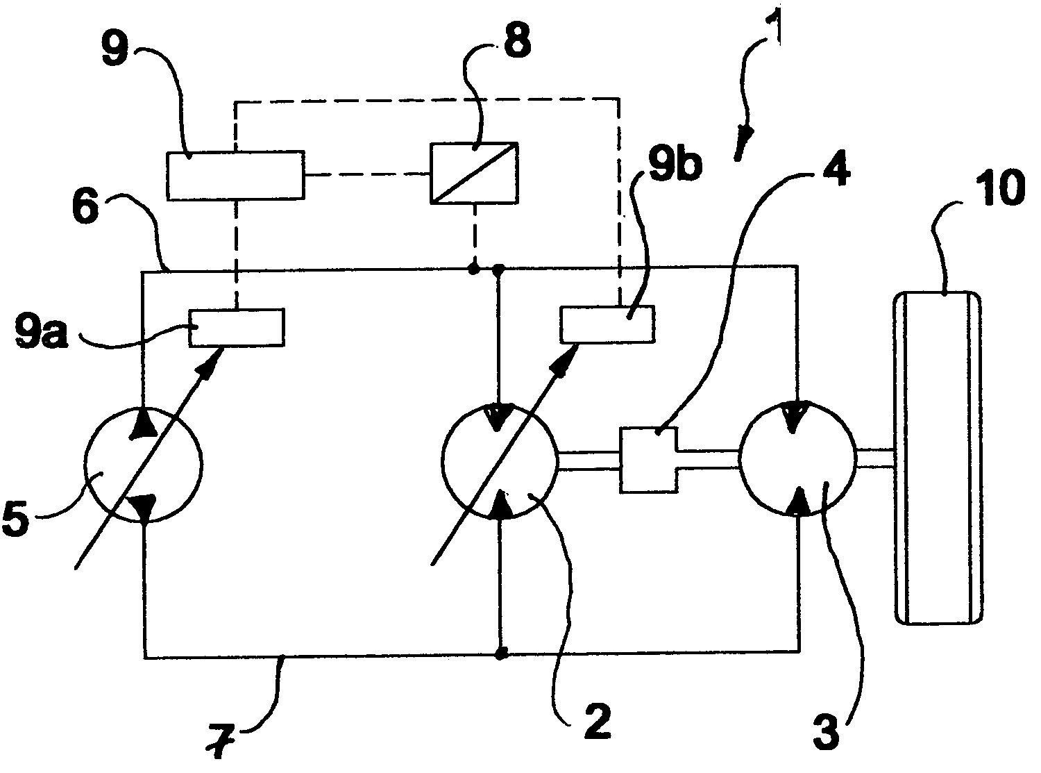
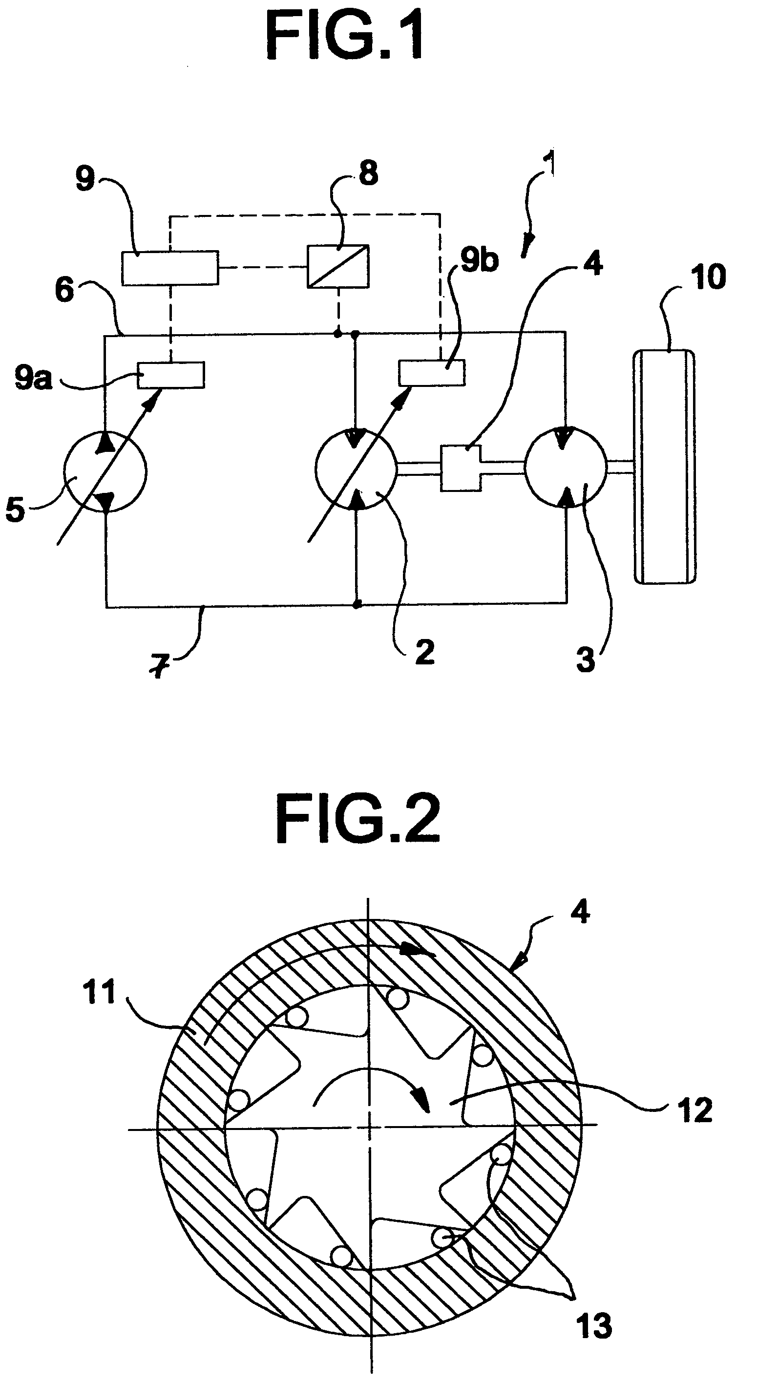
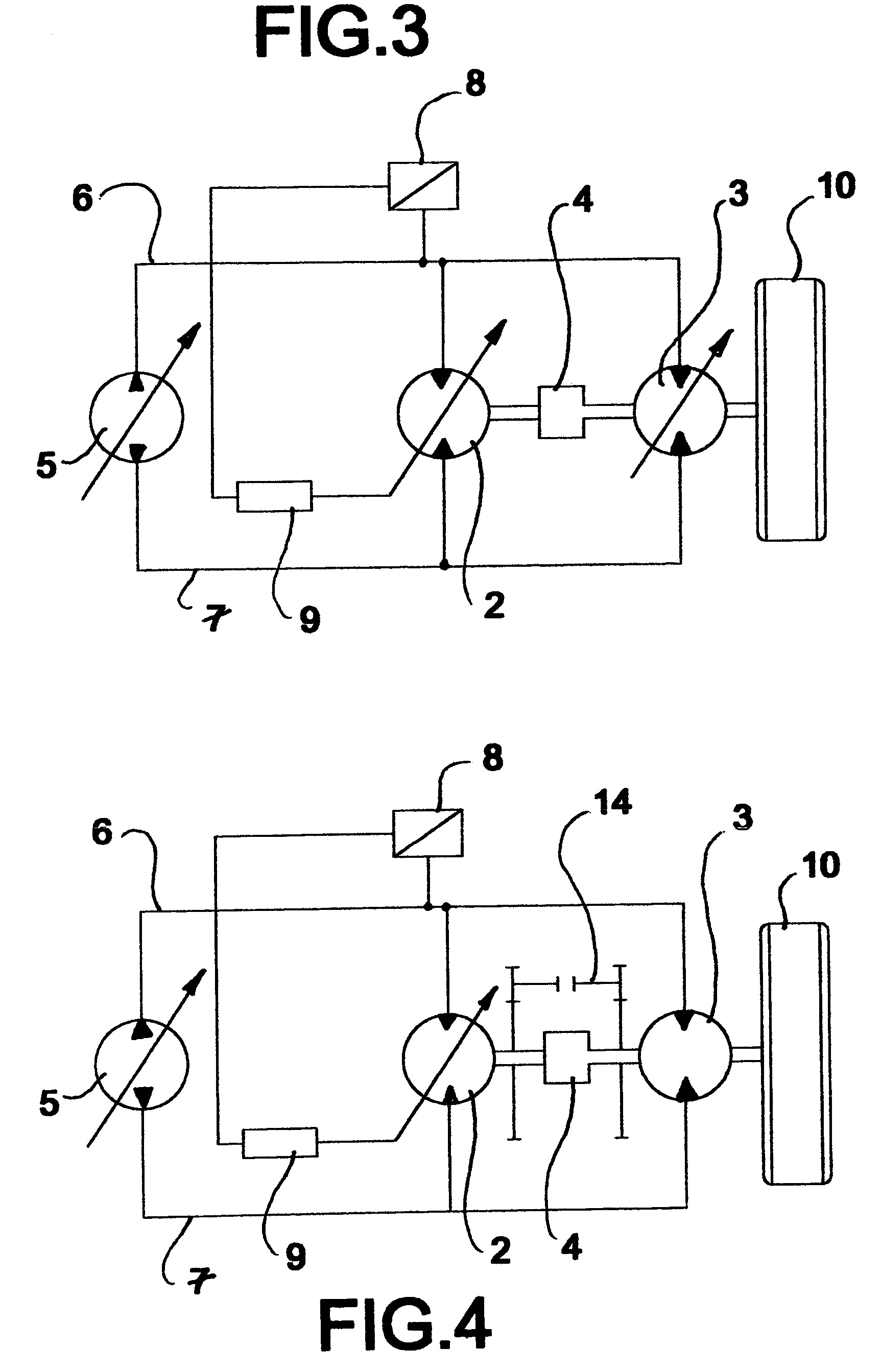
[0020]Referring to FIG. 1, a multi-motor drive unit in accordance with the invention, generally designated by 1, comprises a hydraulic motor 2 which is variable in its displacement volume and a hydraulic motor 3 with a constant displacement volume. These are interconnected via a mechanical freewheel device 4. A variable displacement hydraulic pump 5 provides the hydraulic circuit with pressure medium via pipes 6 and 7.

[0021]At least one pressure sensor with a measurement signal transformer 8 measures the pressure in the hydraulic circuit and passes it on in the form of an electrical signal to a control unit 9. This calculates from the measured parameters of status in the circuit and the desired values prescribed by the user, the correcting signals, and with these adjusts the volume of the variable motor 2 through the motor controller 9b and with the pump controller 9a adjusts the displacement volume of the variable displacement pump 5.

[0022]Thus, depending upon the volume flow of pu...


PUM


Abstract

With a hydrostatic multi-motor drive unit with a least two hydraulic motors acting upon a common load, a solution should be created, with which a further operating range is covered by the use of several motors and at the same time a simple as possible and problem free coupling of the motors is assured. Furthermore, a method for controlling the drive unit is indicated, which permits continuous transitions between the different operating ranges. This is achieved in that the motors (2, 3) are connected with each other through at least one freewheel device (4), in which the motor (2) arranged after the freewheel device has a variable displacement volume.

Description

BACKGROUND OF THE INVENTION[0001]The present invention relates to hydrostatic multi-motor drive units and, more particularly, to such a unit with at least two hydraulic motors acting upon a common load.[0002]Hydraulic drives with two motors are known in essentially two different versions or designs.[0003]In a first design both drives are rigidly interconnected by a shaft and, hence, both run permanently. In arrangements in which at least one of the motors is designed to be adjustable, and for attaining high speeds, this motor is set to zero by adjusting its displacement volume to zero. It is disadvantageous that the motor which is set to zero is dragged along by the other motor and, as a result of this, high mechanical losses occur.[0004]To avoid such problems, two-motor drive designs are known in which the two motors are interconnected by gears and couplings, so that in the operating ranges in which the adjustable motor is set to zero, this motor can be mechanically disconnected fr...

Claims


Application Information

Patent Timeline
Patent Type & Authority Patents(United States)
IPC IPC(8): F16D31/02F16H61/425F16H61/435F16H61/448
CPCF16H61/425F16H61/435F16H61/44F16H61/448F16H2059/6853F16H2059/6861
Inventor IVANTYSYNOVA, MONIKAWEBER, JURGEN
Owner CNH BAUMASCHEN
Why Eureka
Try Eureka