Digitally controlled corrosion protection system and method

a corrosion protection system and digital control technology, applied in the field of digital control corrosion protection systems and methods, can solve the problems of corrosion problem, metal structure (such as iron or iron alloy structure), water subject to significant problems, etc., and achieve optimal protection of structure or structure, reduce any induced signal errors, and ensure the effect of corrosion prevention

Active Publication Date: 2014-09-18
FREEMAN INDAL
View PDF19 Cites 7 Cited by
  • Summary
  • Abstract
  • Description
  • Claims
  • Application Information

AI Technical Summary

Benefits of technology

[0015]The present invention has several advantages over existing corrosion protection systems and methods. It does not require manual or analog adjustment of a direct current (DC) or rectified alternating current (AC) power supply for control, but can use pulse width modulation (PWM) control instead. It does not depend on an analog error signal to produce the current output, and therefore has more precise control than existing analog corrosion protection systems and methods. A normal difference between actual and desired Reference Cell voltages in the present invention is usually between 0 to 5 millivolts, unlike the 25 millivolt difference in some analog existing analog corrosion protection systems and methods.
[0016]In addition, the present invention allows the sample time for measuring Reference Cell voltages to be sufficiently long so as to negate any induced voltages from extraneous sources. Also, the present invention can take multiple samples, and mathematically average them in order to reduce a

Problems solved by technology

A metal structure (such as an iron or iron alloy structure) which must be immersed in an electrolyte (such as water) is subjected to a significant problem: corrosion.
This corrosion problem occurs due to a flow of electrical current through the electrolyte, between localized Cathodic and Anodic portions of the immersed structure.
Furthermore, in either case, it is desirable to maintain the structure at a predetermined potential in order to continue to prevent corrosion, since an improper potential level can reduce the effectiveness of corrosion protection, and, in some cases, actually stimulate the corrosion.
However, existing analog corrosion protection systems have many drawbacks and limitations.
For example, the corrosion protection system disclosed in U.S. Pat. No. 4,437,957, to Freeman, issued on Mar. 20, 1984, has many limitations.
The analog system disclosed in Freeman can only control one Anode array for

Method used


Image

  • Digitally controlled corrosion protection system and method
  • Digitally controlled corrosion protection system and method
  • Digitally controlled corrosion protection system and method

Examples


Embodiment Construction

[0054]One of the key issues in system design is getting the hardware and the firmware to work together properly. The combined system must perform the desired function in the end. In this case, the purpose of the system is to provide current flow in a Cathodic protection system, to an extent that the structure in the protected system does not corrode.

[0055]In the present invention, the system is connected to a power supply that typically provides 12 volts DC to the system, and the Digital Controller is required to properly regulate the current flow in the system to provide maximum corrosion protection to the system within required parameters without over charging the system.

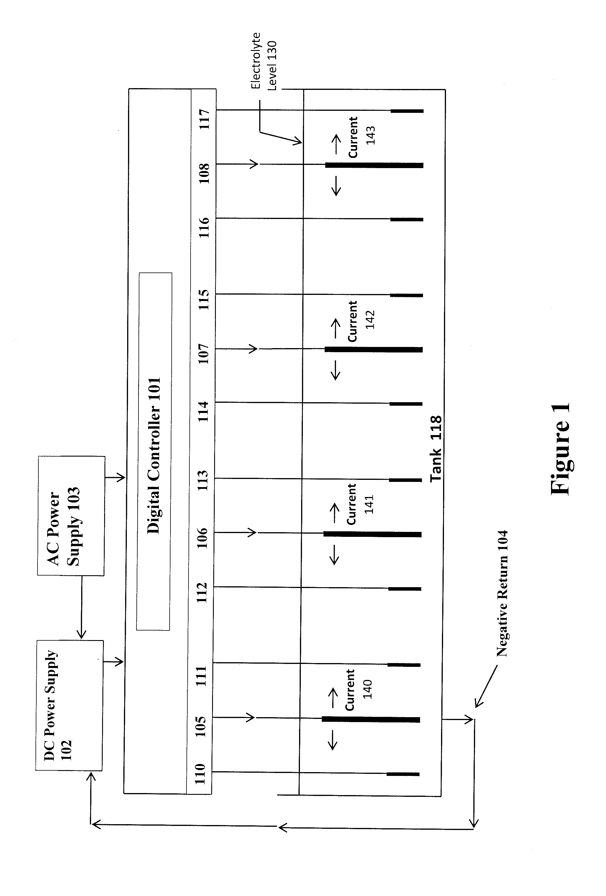
[0056]FIG. 1 depicts a structure (Tank 118) that is protected by an example embodiment of the invention. At the top right of the graphic is the AC Power Supply 103, which supplies power to the DC Power Supply 102 as well as the Digital Controller 101. In the example embodiment, the Digital Controller 101 has four ...


PUM


Abstract

At least one corrosion protection unit is located adjacent to a region of a structure immersed in an electrolyte. Each corrosion protection unit includes a circuit for applying rectified alternating current voltage between the structure and electrodes in the electrolyte. Each corrosion protection unit includes Reference Cells to produce direct current voltage between the Reference Cells and the structure, a measuring circuit coupled to the Reference Cells for measuring the potential between the Reference Cells and the structure, and a control circuit for controlling the level of the rectified alternating current voltage in accordance with the measured potential levels. Corrosion protection units are independent of one another, so that independently established rectified alternating current voltages are applied between different regions of the structure and e first and second corrosion protection units. Alternatively, the corrosion protection units apply constant current or constant voltage instead of Reference Cell feedback control.

Description

CROSS-REFERENCE TO OTHER APPLICATIONS[0001]This application claims the benefit of Provisional U.S. Patent Application No. 61 / 789,634, the disclosure of which is herein incorporated by reference. In addition, the disclosure of U.S. Pat. No. 4,437,957 is also herein incorporated by reference.FIELD OF THE INVENTION[0002]The present invention relates generally to digitally controlled corrosion protection systems and methods, and, more particularly, to a system and method for independently providing corrosion protection to different regions of a protected structure, or to a plurality of different protected structures.BACKGROUND OF THE INVENTION[0003]A metal structure (such as an iron or iron alloy structure) which must be immersed in an electrolyte (such as water) is subjected to a significant problem: corrosion. This corrosion problem occurs due to a flow of electrical current through the electrolyte, between localized Cathodic and Anodic portions of the immersed structure.[0004]Accordi...

Claims


Application Information

Patent Timeline
IPC IPC(8): C23F13/04
CPCC23F13/04G01N17/02
Inventor FREEMAN, JONATHAN PAULLONG, EDWARD ALYNFREEMAN, ADAM SPENCERFREEMAN, JON ANDREW
Owner FREEMAN INDAL
Why Eureka
Try Eureka