Conveyor system

Inactive Publication Date: 2000-12-05
VALIANT CO LTD
View PDF6 Cites 35 Cited by
  • Summary
  • Abstract
  • Description
  • Claims
  • Application Information

AI Technical Summary

Benefits of technology

A primary advantage of applicant's invention is that, since the entire working conveyor section, together with any work pieces supported by it, are moved between a raised and lower position, different types of work pieces can be effectively conveyed by the conveyor system of the present invention. The present invention, however, has proven particularly effective for conveying automotive bodies on skids.

Problems solved by technology

However, since different automotive bodies may be conveyed by a common conveyor line, it is oftentimes necessary to provide different lifter assemblies at a single work station in order to accommodate these different automotive bodies.

Method used


Image

  • Conveyor system
  • Conveyor system
  • Conveyor system

Examples


Embodiment Construction

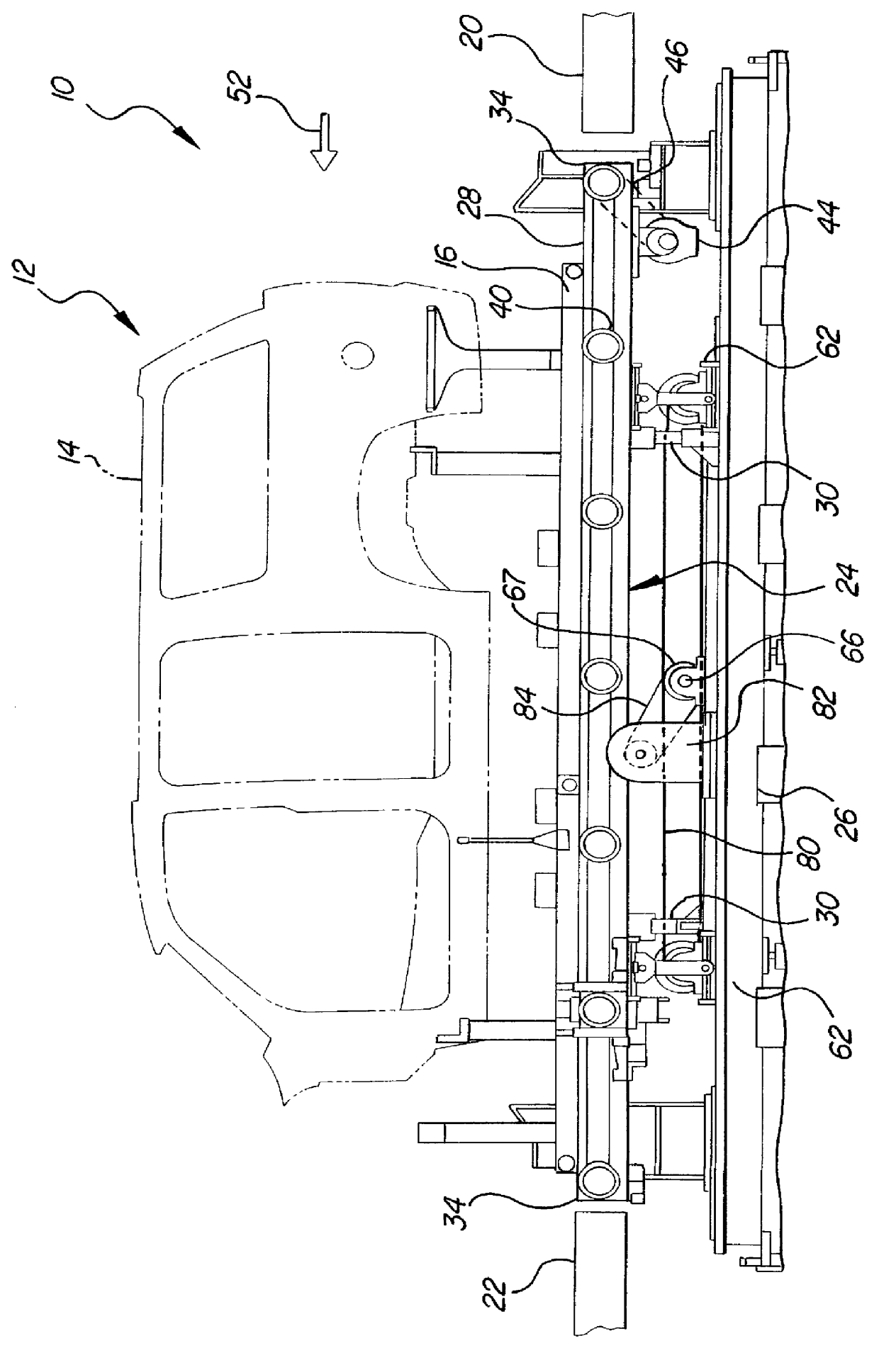
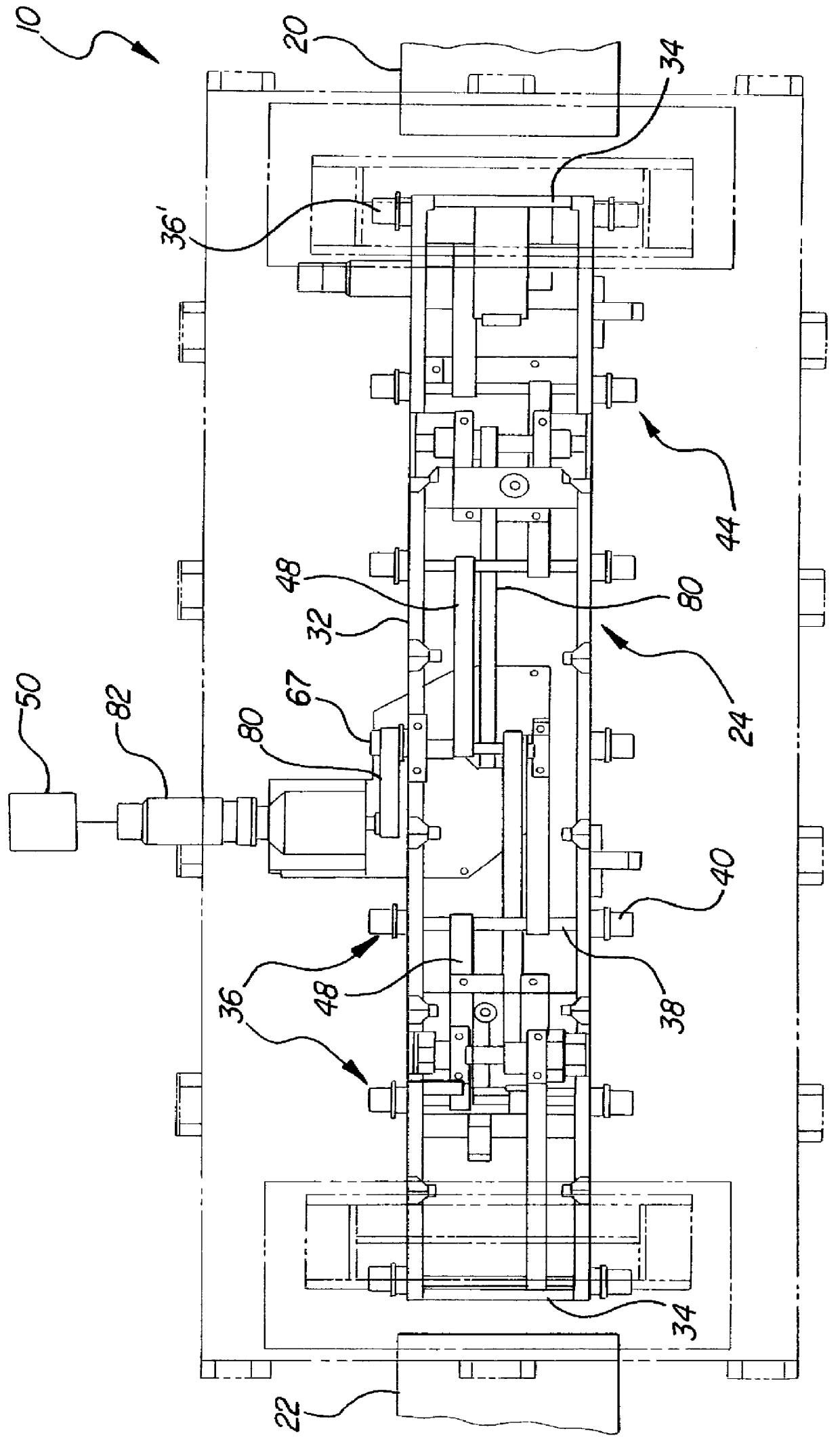
With reference first to FIGS. 1 and 2, a preferred embodiment of the conveyor system 10 of the present invention is there shown for transporting work pieces 12, such as an automotive body 14 supported on a skid 16. The conveyor system 10 includes an infeed conveyor section 20, an outfeed conveyor section 22 and a working conveyor section 24 positioned in between the infeed and outfeed conveyor sections 20 and 22, respectively.

In a fashion which will be subsequently described in greater detail, the working conveyor section 24 is movable between a raised and a lower position. The working conveyor section 24 is illustrated in its lower position in FIG. 1 and, as such, the working conveyor section 24 lies on generally the same horizontal plane as both the infeed and outfeed conveyor sections 20 and 22, respectively. As such, the working conveyor 24 receives the work piece 12 from the infeed conveyor 20 and, upon completion of a work operation, conveys the work piece 12 to the outfeed co...


PUM


Abstract

A conveyor system having an infeed conveyor section, an outfeed conveyor section, and a working conveyor section positioned in between and in line with the infeed and outfeed conveyor sections. The working conveyor section includes a base and a frame which is movably mounted relative to the base between a lower position and a raised position. In order to move the frame between its lower and raised position, a driver is rotatably mounted about a substantially horizontal axis to the base while an elongated drive link has one end pivotally connected to the frame and its other end pivotally connected to the driver at a position radially spaced from its axis. A drive mechanism selectively pivots the driver between first and second rotational positions which are spaced substantially 180 degrees from each other. In doing so, the coaction between the driver and the drive link moves the frame between its raised and lowered position.

Description

I. Field of the InventionThe present invention relates to conveyor systems.II. Description of the Prior ArtThere are many previously known conveyor systems. In one type of conveyor system, rollers engage work pieces supported on the conveyor system in order to propel the work pieces from one end of the conveyor system and toward the other end. In many cases, one or more work stations are positioned along the conveyor line in order to perform work of one sort or another upon the work pieces.These previously known roller conveyor systems typically propel the work pieces along a generally horizontal plane. In some instances, such as the assembly of an automotive body, it is desirable or even necessary to elevate the work piece above the plane of the conveyor line at a particular work station and before the work is performed on the work piece.In order to accomplish the elevation of the work piece at a particular work station, it has been the previously known practice to provide a lifter...

Claims


Application Information

Patent Timeline
Patent Type & Authority Patents(United States)
IPC IPC(8): B62D65/18B62D65/00
CPCB62D65/18
Inventor MURPHY, PATRICK M.
Owner VALIANT CO LTD
Why Eureka
Try Eureka