Extended wear pump diaphragm

a diaphragm and extended wear technology, applied in the direction of engine diaphragms, flexible wall reciprocating engines, positive displacement engines, etc., can solve the problems of increasing the risk of diaphragm damage, and causing significant wear and tear. , to achieve the effect of resisting significant wear

Inactive Publication Date: 2000-12-12
WESTINGHOUSE AIR BRAKE CO
View PDF2 Cites 36 Cited by
  • Summary
  • Abstract
  • Description
  • Claims
  • Application Information

AI Technical Summary

Problems solved by technology

However, the constant flexing of certain portions of the diaphragm when the pump is in use creates stresses on the nonflexing portions of the diaphragm that are attached to the pump.
These areas of the diaphragm which are in movable contact with these followers and flanges will normally exhibit rather severe wear and, after extended use with the constant flexing of the diaphragm, will eventually crack and / or have holes wear through the diaphragm.
It is primarily at the wear points of such diaphragm caused by the relative movement between the diaphragm and the follower and flange members, under normal circumstances, that the diaphragm will reveal major problems.
The replacement of the diaphragm, however, is only one of the problems that maintenance personnel encounter.
The location of many pumps is such that not only may they be very difficult to get to but, even after reaching the pump, performing the work of replacing a diaphragm can and oftentimes does present a real challenge.

Method used


Image

  • Extended wear pump diaphragm
  • Extended wear pump diaphragm
  • Extended wear pump diaphragm

Examples


Embodiment Construction

Prior to proceeding to the more detailed description of the present invention, it should be noted that for the sake of clarity in understanding the invention, identical components with identical functions have been designated with identical reference numerals throughout the drawing Figures.

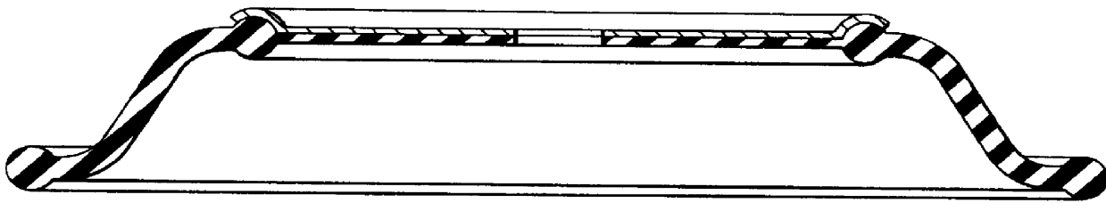
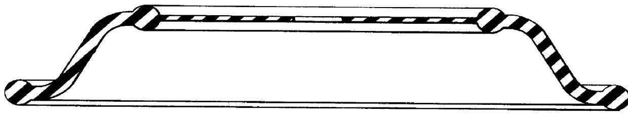
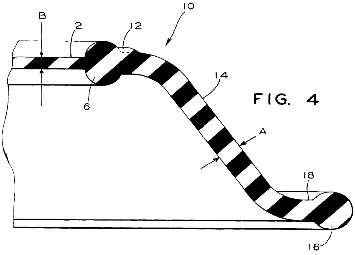
Illustrated in FIGS. 1 and 2 are cross-sectional views of a diaphragm as used in prior art, with FIG. 2 including an outer piston. FIGS. 3 and 4 depict a diaphragm, generally designated 10, showing the embodiment of the present invention.

Such diaphragm 10 has an outer bead like portion 16. Such outer bead like portion 16 has a first predetermined configuration and is used to secure diaphragm 10 to a pump housing (not shown). In a presently preferred embodiment of the invention such first predetermined configuration is generally round.

Diaphragm 10 has a annular flexure portion 14 having a first end 18 and a second end 22. First end 18 and second end 22 of such annular flexure portion 14 are general...


PUM


Abstract

The present invention provides a diaphragm for use in pump applications in which at least a predetermined portion of such diaphragm is in contact with such outer piston which would tend to abrade such diaphragm. Such diaphragm is formed from at least one layer of a preselected flexible material. Such diaphragm comprises an outer bead like portion for securing the diaphragm to a pump housing. There is a annular flexure portion having a first end and a second end, such first end and such second end being generally flat and an arcuate shaped middle portion formed contiguously with the first end and the second end. Such first end is formed contiguously with the outer bead like portion. Such annular flexure portion has a substantially uniform first predetermined thickness. An enlarged bulbous portion is formed contiguously with the second end and extends around an inner periphery thereof. Such enlarged bulbous portion has a predetermined configuration. Such diaphragm has an enlarged section formed as a protrusion that extends outwardly from an outer surface of the generally flat second end. Such enlarged section is formed contiguously with the enlarged bulbous portion and extends around an outer periphery thereof. The enlarged section causes the second end to be thicker than such first predetermined thickness. Further, there is a generally flat center portion that is formed contiguously with the enlarged bulbous portion and extends around an inner periphery thereof.

Description

The present invention relates, in general, to diaphragms which are subjected to detrimental wear during service due to abrasion caused by contact with nonflexing type surfaces which move relative to such diaphragms when used in pumps and pumping systems and, more particularly, this invention relates to diaphragms that have been modified to substantially reduce such abrasion and wear in the area of the diaphragm that is in contact with the nonflexing surfaces where wear is most likely to occur.As is generally well known in the prior art, diaphragms are an integral part of pumps. It is necessary in these applications for the diaphragms to be flexible in order for them to perform their intended function. However, the constant flexing of certain portions of the diaphragm when the pump is in use creates stresses on the nonflexing portions of the diaphragm that are attached to the pump.In these type pumps there is a follower and flange which support the diaphragm and help to secure it in ...

Claims


Application Information

Patent Timeline
Patent Type & Authority Patents(United States)
IPC IPC(8): F04B43/00F16J3/02F16J3/00
CPCF04B43/0063F16J3/02F05C2225/00
Inventor HUSS, HOWARD D.
Owner WESTINGHOUSE AIR BRAKE CO
Why Eureka
Try Eureka