Device for reducing firearms trigger pull weight

a technology for reducing the weight of the trigger, applied in the field of firearms, can solve the problems of reducing the leverage advantage, drilling the hole of the firearm, and the disadvantage of prior art pivoting trigger devices

Inactive Publication Date: 2000-12-26
LEE ROBERTO R
View PDF10 Cites 41 Cited by
  • Summary
  • Abstract
  • Description
  • Claims
  • Application Information

AI Technical Summary

Problems solved by technology

U.S. Pat. No. 5,955,155 to Jones which discloses a leverage to reduce the felt trigger pull weigh, however, the line of resisting load or force from the stirrup position is so arranged being in-line with the trigger finger will eventually minimizes leverage advantage and also requires drilling hole on the firearms.
(a) The prior arts single piece triggers are mow made of different combination of lightweight materials but still do not reduce trigger pull weight.
(b) The prior art pivoting trigger device is obviously disadvantageous since the basic straight pull is being altered into a pivoting trigger pull action and produces inconsistent trigger pull weight each time the trigger finger depresses the pivot trigger set closer or farther away from the pivot pin.
The prior art pivoting trigger device is also highly disadvantageous since it discloses the need for drilling and threading of hole on firearms upon installation.
(d) The prior art pivoting trigger device discloses a fixed stirrup post which requires trim cutting for obtaining correct contact between the sear, stirrup and the pivoting trigger by trial and error method and req...

Method used


Image

  • Device for reducing firearms trigger pull weight
  • Device for reducing firearms trigger pull weight
  • Device for reducing firearms trigger pull weight

Examples


Embodiment Construction

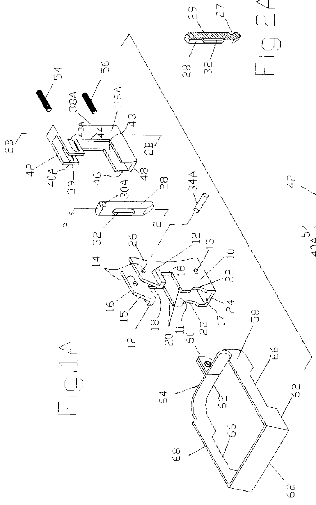
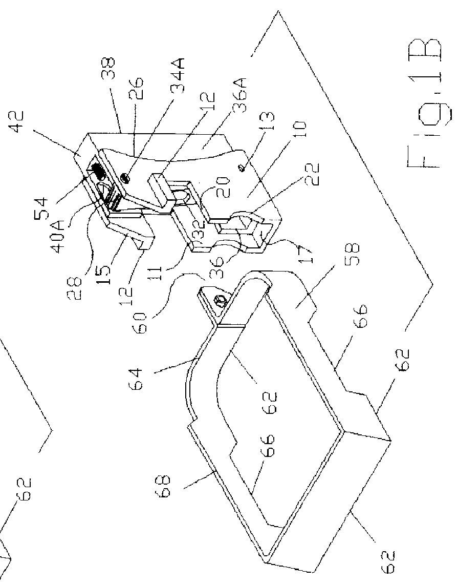
Description--FIGS. 1A, 1B, 2A, 2B

A preferred embodiment of a trigger converter of the present invention is illustrated in FIG. 1A and FIG. 1B (perspective views). The trigger converter being equipped of an enclosure 10 provided with catch 12 on each side that allows self-anchoring to the receive spacer tunnel 83. Plurality of bearing surfaces 11 and 17 arranged on the center to allow a secondary enclosure 36A to slide to and fro.

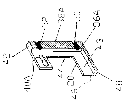
The enclosure of the converter device has a link hole 14 that passes through on each side for inserting a link pin 34A for retaining a link 28 and also retains the secondary enclosure 36A through slot 40A that will allow secondary enclosure to slide to and fro. Also, the enclosure has a button recess 22 for engaging with a changer button 70 with a sliding fit and above the button recess is provided with a spacer recess 20 that allow the overlapping guide 64 and spacer nose 60 on spacer 58 to overlap inside.

The secondary enclosure of the converter has a verti...


PUM


Abstract

A device comprises of independent trigger bow (58) supplied with overlapping recess (64) and a trigger block (10) having a bow guide recess (20), pivot hole (14) with axis pin (34A), primary lever (28) having a axis hole (30) at one end and a bow extender recess (32) and a trigger plate (36A) having a pre-load bar (56) and stopper bar (54) that can be assembled into a module to allow easy installation on trigger tunnel (85) of firearm(88) for reduce firearm trigger pull weight without altering firearm (88). Block (10) is being equipped with catches (12) extending sideways and adjacent with bow guide recess (20) which will overlap with recess (64) of bow (58) to allow both the bow (58) and block (10) to occupy in one same area which allow anchoring against a bow tunnel (83) end wall and supplied with magazine cut (15) disposed on the upper left of block (10) to allow for a magazine passage. As trigger plate (36A) is depressed with finger within a given point on trigger plate (36A) upon firing the finger force will be shifted directly into the adjustable preload bar (56) and synchronizes into the outermost lever end at point (27) of lever (28) producing a high torque leverage which reduces firearm trigger pull weight or load force from the trigger bow (58) energized from sear (70), hammer (72) and hammer spring (82). The trigger plate (36A) being retained with pivot pin (34A) through retaining slot (40A) is supplied with plate bearing (42) and bottom bearing (48) will slide against a frame upper bearing (79) and against s block plate bearing (17) of block (10) respectively, will function as an advancing global pivot point which will changed a rotational action of lever (28) into a linear straight pull action to maintain firearm standard straight action and reducing the trigger pull weight.

Description

1. Field of InventionThis invention relates to firearms and more particularly to a new device wherein the applied trigger finger force is being multiplied to reduce firearms trigger pull weight.2. Description of Prior ArtOriginally, automatic firearms such as a John Browning 1911 series, modified and improved versions are being supplied with a standard trigger that are made of rigid single or integral piece trigger bar assembly having a sliding or linear straight pull action when depressed upon firing.In target shooting competitions and for other special use, firearms are mostly being altered or adjusted to reduce the trigger pull weight by narrowing the engagements between the hammer sear and sear as well as adjustments to springs and other related parts to increase accuracy. The standard integral piece trigger is often replaced with after market light weight trigger bars which minimizes vibration momentum that causes premature hammer fall or hammer follow also of integral piece.Th...

Claims


Application Information

Patent Timeline
IPC IPC(8): F41A19/00F41A19/17F41A19/10
CPCF41A19/17F41A19/10
Inventor LEE, ROBERTO R.
Owner LEE ROBERTO R
Why Eureka
Try Eureka