Device for supplying upper thread of sewing machine

a technology for sewing machines and upper threads, applied in sewing apparatuses, thin material handling, textiles and paper, etc., can solve the problems of tangling of upper threads, defective stitches, and inability to properly feed out upper threads

Inactive Publication Date: 2001-01-02
BROTHER KOGYO KK
View PDF6 Cites 0 Cited by
  • Summary
  • Abstract
  • Description
  • Claims
  • Application Information

AI Technical Summary

Problems solved by technology

When oil or dust cling to the outer surface of the drive roller, the thread can slip so that the upper thread cannot be properly fed out.
Also, the slave rollers have low friction with respect to the upper thread, so they cannot suitably hold the upper thread when the rollers are stopped.
This can result in excessive upper thread being drawn out from the thread spool, resulting in tangling of the upper thread, or in defective stitches.
However, the upper thread is not stably feed out when both of the slave rollers have the same configuration.
Improper thread feed has an adverse effect on stitches.
Also, when a quench-hardened metal is used for the drive roller, the resin slave rollers are quickly worn down to a smooth surface and are not very durable.
That is, because the resin thread contacting portions of slave rollers are quickly worn down to a low friction coefficient, they are incapable of stably feeding out the upper thread.
As a result of the unstable thread feed, the upper thread can slip and carve into the resin thread contacting portion of the slave rollers.
Grooves and scratches formed in the thread contacting portions causes the upper thread to break or cause improper holding of the upper thread.
When the upper thread slips, tangling thread can result.

Method used


Image

  • Device for supplying upper thread of sewing machine
  • Device for supplying upper thread of sewing machine
  • Device for supplying upper thread of sewing machine

Examples


Embodiment Construction

An upper thread supply device 1 according to an embodiment of the present invention will be described while referring to the accompanying drawings wherein like parts and components are designated by the same reference numerals to avoid duplicating description.

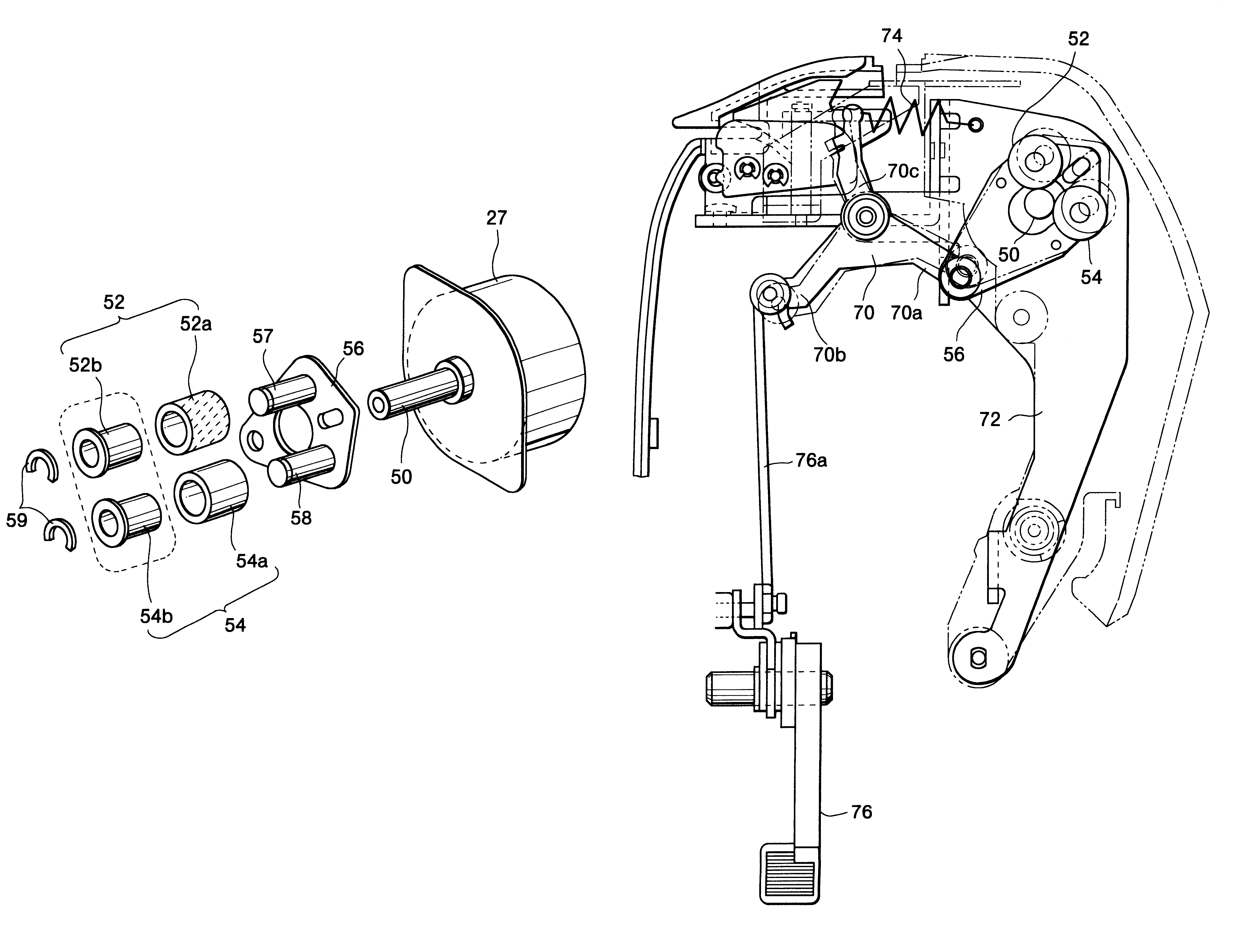
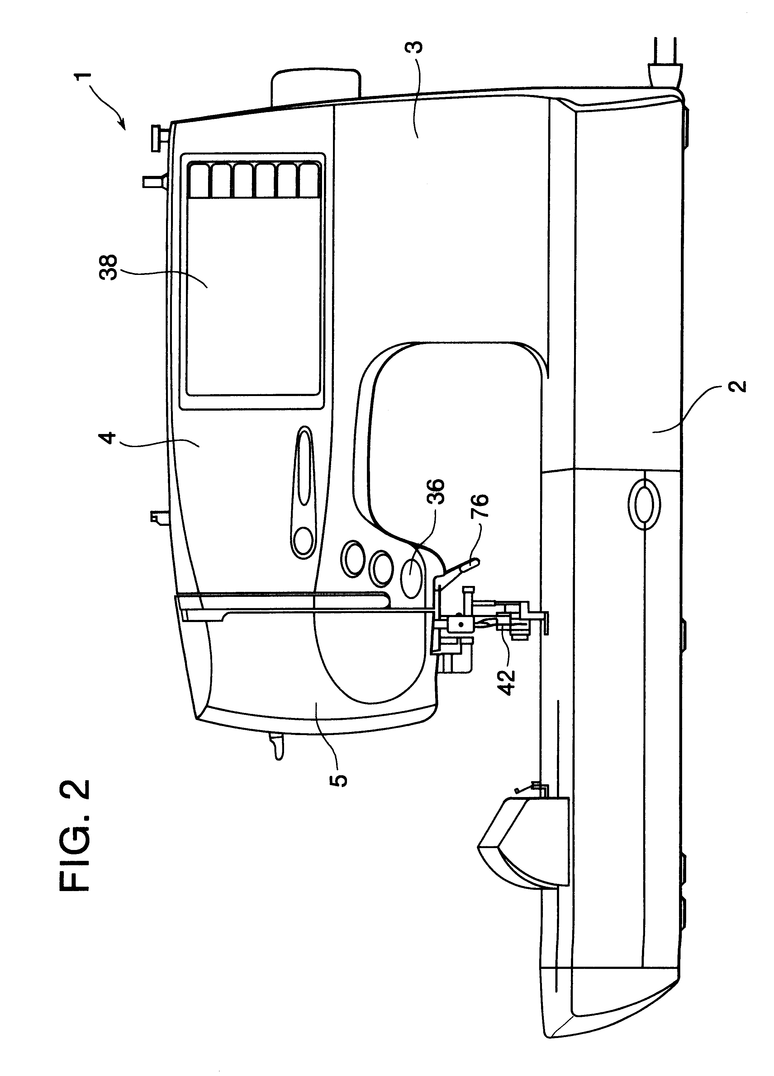
FIG. 2 shows a sewing machine 1. The sewing machine 1 includes a bed 2, a column 3 extending upward from the bed 2, an arm 4 extending from the column 3 over the bed 2, and a head 5 connected to a free end of the arm 4. The sewing machine 1 also includes a start / stop key 36 for starting and stopping sewing operations, and a liquid crystal display 38 for displaying settings and warning messages, for example.

As shown in FIG. 3, the sewing machine 1 includes a CPU 20, a RAM 28, and a RAM 30. The CPU 20 is connected, via an output interface, to a sewing machine motor 22, a feed dog pulse motor 24, a needle swing pulse motor 26, and an upper thread feed pulse motor 27. The CPU 20 controls drive of these motors according to a program...


PUM


Abstract

An upper thread supply device includes a drive roller 50 and two slave rollers 52, 54. The slave roller 52 has a thread contacting portion 52a formed from a soft metal. The slave roller 54 has a thread contacting portion 54a formed from a resilient material. The drive roller 50 is formed from a hard metal. A thread is supplied by the upper thread supply device following a thread feed pathway. The drive roller 50 and the soft metal thread contacting portion 52a sandwich the thread at one position along the thread feed pathway and the drive roller 50 and the resilient thread portion 54a sandwich the thread at a separated position along the thread feed pathway. The resilient thread contacting portion 54a is positioned downstream from the position where the thread is sandwiched by the hard metal thread contacting portion 54a and the soft metal thread contacting portion 52a. The hard metal thread contacting portion of the drive roller 50 and the soft metal thread contacting portion 52a sandwich the thread and prevent it from being excessively drawn out from the thread spool by vertical movement of a thread take-up lever. The hard metal drive roller 50 and the resilient thread contacting portion 54a mainly reliably feed out the upper thread by sandwiching the upper thread there-between.

Description

1. Field of the InventionThe present invention relates to an upper thread supply device having a drive roller driven by a drive motor and a slave roller disposed in contact with the drive roller. The drive roller and the slave roller hold a thread there-between and feed the thread by rotation of the drive roller.2. Description of the Related ArtJapanese Utility-Model-Application Publication (Kokai) No. HEI-1-111581 discloses an upper thread supply device with a drive roller and two slave rollers that all extend parallel to each other. The slave rollers are disposed adjacent to the drive roller. Drive force from a motor is transmitted to the drive roller by gears. A thread is sandwiched between the drive roller and the slave rollers, and fed out by rotation of the drive roller.FIG. 1 shows another conventional upper thread supply device. The device includes a drive roller 158 fixed to the drive shaft of a drive motor 148, and two slave rollers 170, 170. The two slave rollers 170, 170...

Claims


Application Information

Patent Timeline
Patent Type & Authority Patents(United States)
IPC IPC(8): D05B47/00D05B45/00
CPCD05B47/00
Inventor FUNATO, NOBUHIKO
Owner BROTHER KOGYO KK
Why Eureka
Try Eureka