Screwdriver bits

a screwdriver and bit technology, applied in screwdrivers, wrenches, manufacturing tools, etc., can solve the problems of reducing pressure, difficult inability to achieve uniform and superior densification, etc., to achieve uniform, precise and superior densification, superior resistance to bending moments, and superior densification

Inactive Publication Date: 2007-01-30
FELO WERKZEUGFAB HOLLAND LETZ
View PDF21 Cites 35 Cited by
  • Summary
  • Abstract
  • Description
  • Claims
  • Application Information

AI Technical Summary

Benefits of technology

[0014]The invention provides two significant advantages. First, a uniform, precise and superior densification is achieved during the pressing of the blanks such that the region of the penetrating section of the front section has superior resistance to bending moments acting on the cruciform lands during the transmission of torque. A suitable grain size composition of the chosen metal powder mixture can also contribute to this stability. Such a uniform and superior densification was very difficult to achieve until now, in particular, when producing cross-tips, because the compression mold is filled with metal powder to a similar height as that required for manufacturing one-piece screwdriver bits. The pressure exerted on the metal powder filling by the ram does not have a uniform effect that extends up into the region of the tip and the grooves between the lands because this pressure diminishes within the filling due to the friction of the filling on the walls of the mold. Second, the invention ensures that the blanks reach the sintering process without cracks as is required, in particular, for the superior durability of cross-tips. The metal powder that is compressed in the mold under high pressure, and the blank produced thereby, has high resistance to its removal from the mold. This resistance increases proportionally with the surface area of the blank. The resistance to the removal from the mold must be overcome with the force of the ejector pin or bottom die which acts on the central tip. The high specific load on the tip and the ejector force which acts on the cruciform lands may lead to the formation of fine cracks that cannot be remedied during the sintering process and interfere with the homogeneity of the structure. The short design of the hard metal front section in accordance with the invention significantly reduces the required ejector force. Consequently, it is possible, e.g., to eliminate the requirement for a complicated and expensive compression mold in which the bottom die has not only the profile of the central tip but also the profile of the backs of the cruciform lands which conically extend toward the tip, e.g., as is the case in the previously described method [VDI-Zeitschrift No. 7–9 (1999), pp. 42–45].

Problems solved by technology

Such a uniform and superior densification was very difficult to achieve until now, in particular, when producing cross-tips, because the compression mold is filled with metal powder to a similar height as that required for manufacturing one-piece screwdriver bits.
The pressure exerted on the metal powder filling by the ram does not have a uniform effect that extends up into the region of the tip and the grooves between the lands because this pressure diminishes within the filling due to the friction of the filling on the walls of the mold.
The high specific load on the tip and the ejector force which acts on the cruciform lands may lead to the formation of fine cracks that cannot be remedied during the sintering process and interfere with the homogeneity of the structure.

Method used


Image

  • Screwdriver bits
  • Screwdriver bits
  • Screwdriver bits

Examples


Embodiment Construction

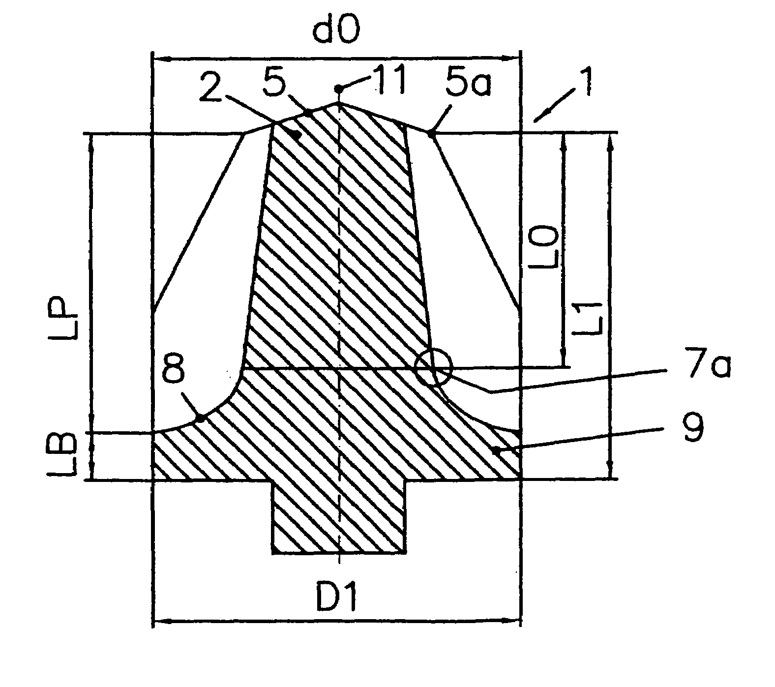
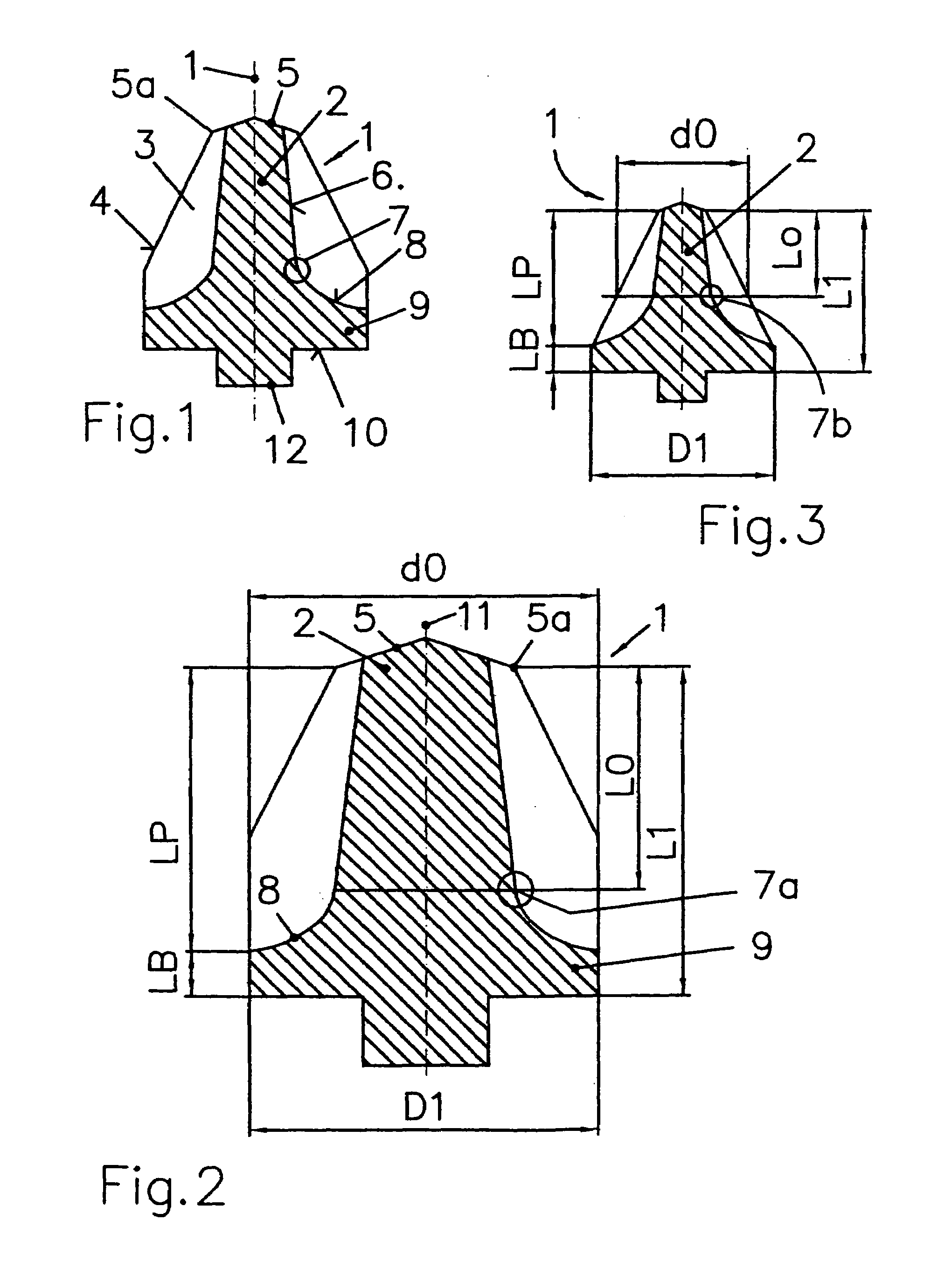
[0052]FIG. 1 shows a front section 1 of a screwdriver bit according to the invention. On its front end, the front section 1 is provided with a penetrating section 2 in the form of a conventional cross-tip that serves for penetrating into the corresponding interior profile of a cross-head screw. The cross-tip contains four ribs or lands 3 that are arranged in cruciform fashion and have upper edges 4 that conically converge toward the front and end at a flattened end section 5 that is insignificant for the purpose of the invention. Cruciform flutes or grooves with groove bottoms 6 that also extend conically up to the end section 5 are arranged between the lands 3, where said groove bottoms are curved or beveled radially outwardly on the side that faces away from the end section 5 beginning at a point 7 that defines the rear end of the penetrating section 2, such that the groove bottoms form a section referred to as the continuation 8 below.

[0053]A base section 9 that, for example, is ...


PUM


Abstract

The invention pertains to a screwdriver bit with a drive section (14) and a front section (1) that contains a profiled penetrating section (2) and is manufactured by compression molding and subsequently sintering a hard metal powder, where the front section is connected to the drive section. Thus, according to the invention, the length of the front section (1) is not greater than 2.5-times the length of the penetrating section (2) and / or the ratio of the length of the front section (1) to the diameter or the width across corners of the penetrating section (2) is not greater than 2.2 (FIG. 7).

Description

RELATED APPLICATION[0001]This application is a continuation of application Ser. No. 09 / 992,900, filed Nov. 6, 2001 now abandoned, which is a continuation-in-part of application PCT / DE01 / 00852, filed Mar. 6, 2001, which designates the United States of America. The entire contents of PCT / DE01 / 00852 are hereby incorporated by reference in their entireties.FIELD OF THE INVENTION[0002]The invention pertains to a screwdriver bit, particularly a screwdriver bit for use with power screwdrivers.BACKGROUND OF THE INVENTION[0003]Screwdriver bits of this type have thus far been manufactured from alloyed tool steels that usually contain carbon and alloying additions, such as silicon, manganese, chrome, molybdenum and vanadium, in fractions of less than 1%. After hardening and tempering, these steels have a hardness of approximately 60–64 HRC. When used with power screwdrivers, the tips of the screwdriver bits manufactured from tool steel suffer from relatively high wear because they are subjecte...

Claims


Application Information

Patent Timeline
Patent Type & Authority Patents(United States)
IPC IPC(8): B25B23/00B25B15/00
CPCB25B15/005B25B15/002
Inventor HOLLAND-LETZ, HORST
Owner FELO WERKZEUGFAB HOLLAND LETZ
Why Eureka
Try Eureka