Metal gasket for cylinder head

a technology of cylinder head and gasket, which is applied in the direction of engine sealing, machine/engine sealing, etc., can solve the problems of high cost of gasket, difficult alignment, and inability to set the step amount at high accuracy, and achieve high heat resistance and sealing properties. high

Inactive Publication Date: 2006-10-19
NIPPON LEAKLESS IND CO LTD +1
View PDF15 Cites 35 Cited by
  • Summary
  • Abstract
  • Description
  • Claims
  • Application Information

AI Technical Summary

Benefits of technology

[0014] According to the metal gasket for a cylinder head described above, the hard metal-plated layer formed on at least one surface of the auxiliary plate interposed between the two base plates extends from the position more radially inward than each of the annular beads of the base plate to the position radially outward so as to overlap the annular bead of the base plate and to face the top portion of the annular bead, and thereby constitutes a step structure by annularly surrounding the respective cylinder holes on the base plates. Therefore, line pressure to be applied to the top portions of the annular beads on the two base plates is increased, and it is possible to exert a high sealing performance against combustion gas pressure inside the cylinder bores. Moreover, according to this metal gasket, the hard metal-plated layer is made of metal. Therefore, it is possible to maintain the high sealing performance as the step structure for the annular beads around the cylinder holes exposed to high heat in particular. Meanwhile, since the hard metal-plated layer is formed in accordance with a plating process, it is also easy to adjust the thickness thereof. In this way, it is possible to obtain an amount of the step easily for optimizing balance of constriction forces between the annular bead and the outer peripheral bead.
[0030] Here, in the metal gasket of this invention, as described in claim 3, the soft surface metal-plated layer is preferably formed as a single layer or a plurality of layers using any of tin, copper, silver, and alloys thereof, and preferably has the surface hardness equal to or below Hv 60. When the surface hardness is low, it is easier to bury small scratches and processing scars on the deck surfaces.

Problems solved by technology

However, in the conventional step structure S1 described in the first place, it is difficult to align the cylinder hole peripheral portions 3a with the outer portions 3b to form a predetermined gasket shape.
Accordingly, there has been a problem that a gasket becomes expensive because an exclusive alignment jig and a high-precision laser welding machine are indispensable for satisfying high precision required in the gasket shape.
Therefore, it is not possible to set the amount of the step at high accuracy in the 10-μm (0.01-mm) order and it is also difficult to ensure the function of the step with a thin plate having the thickness equal to or below 100 μm due to occurrence of distortion, deformation or a lift caused by laser welding.
Accordingly, there has been a problem that a gasket becomes expensive.
Therefore, it is not possible to set the amount of the step at high accuracy in the 10-μm (0.01-mm) order as similar to the second step structure S2.
In addition, the bending and folding process is carried out by use of a drawing process, and the degree of freedom is reduced in terms of the shape of the folded portion 3c. Accordingly, there has been a problem that it is difficult to form the folded portion 3c having a sufficient width in a radial direction without causing cracks especially by use of the thin steel plate.
However, in the former conventional metal gasket, the surface sealing layer is made of a rubber material and durability is therefore insufficient under a high temperature environment.
Accordingly, there has been a problem that the rubber material may be decomposed or peeled off when continuously used in an environment equal to or above 200° C.
Meanwhile, in the latter conventional metal gasket, the surface sealing layer is made of a solid lubricant material and it is difficult to retain a uniform layer on the surface of the base plate.
Accordingly, there have been problems that it is difficult to ensure a sufficient sealing property and that the degree of freedom of a bead structure is also reduced.

Method used


Image

  • Metal gasket for cylinder head
  • Metal gasket for cylinder head
  • Metal gasket for cylinder head

Examples


Embodiment Construction

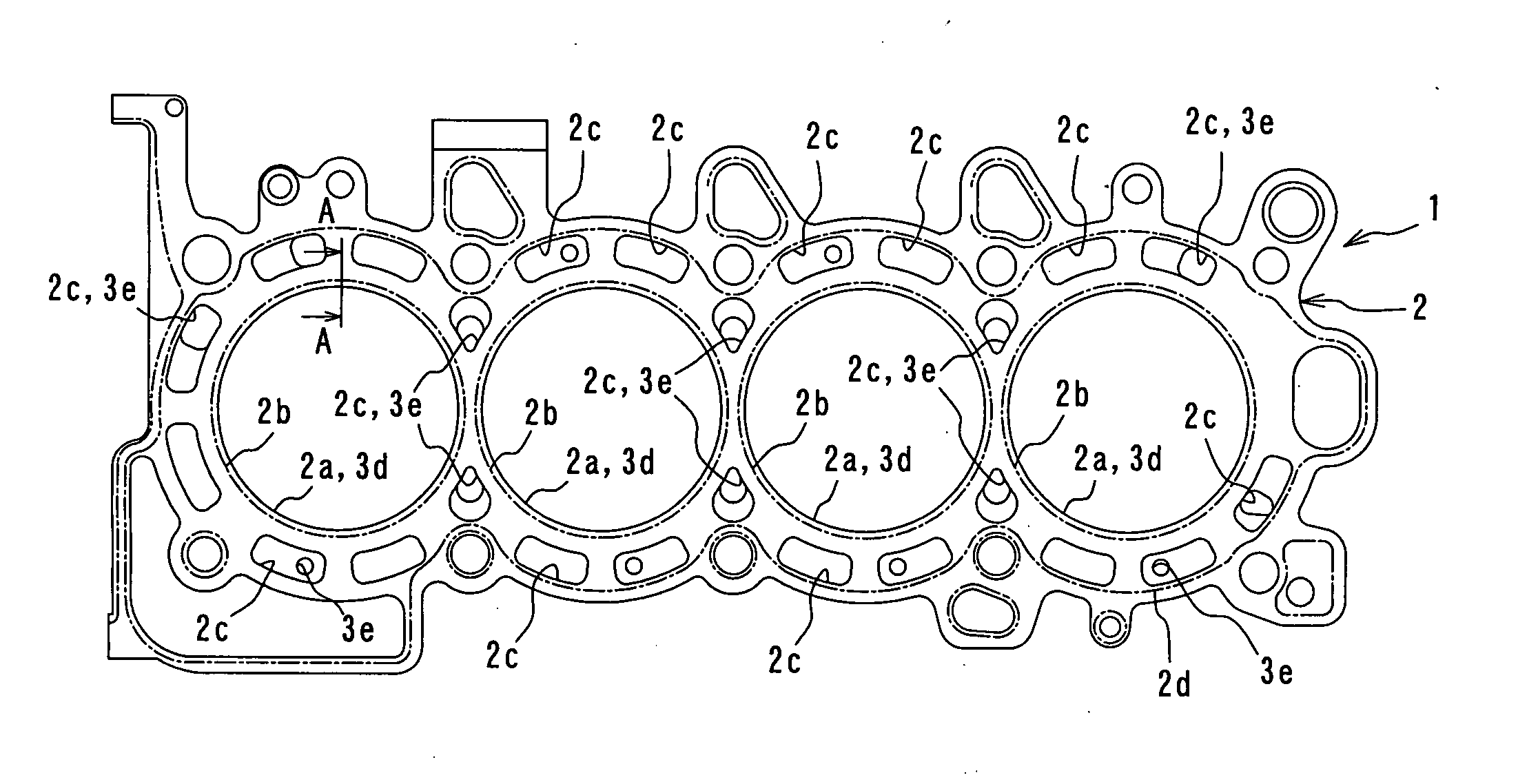
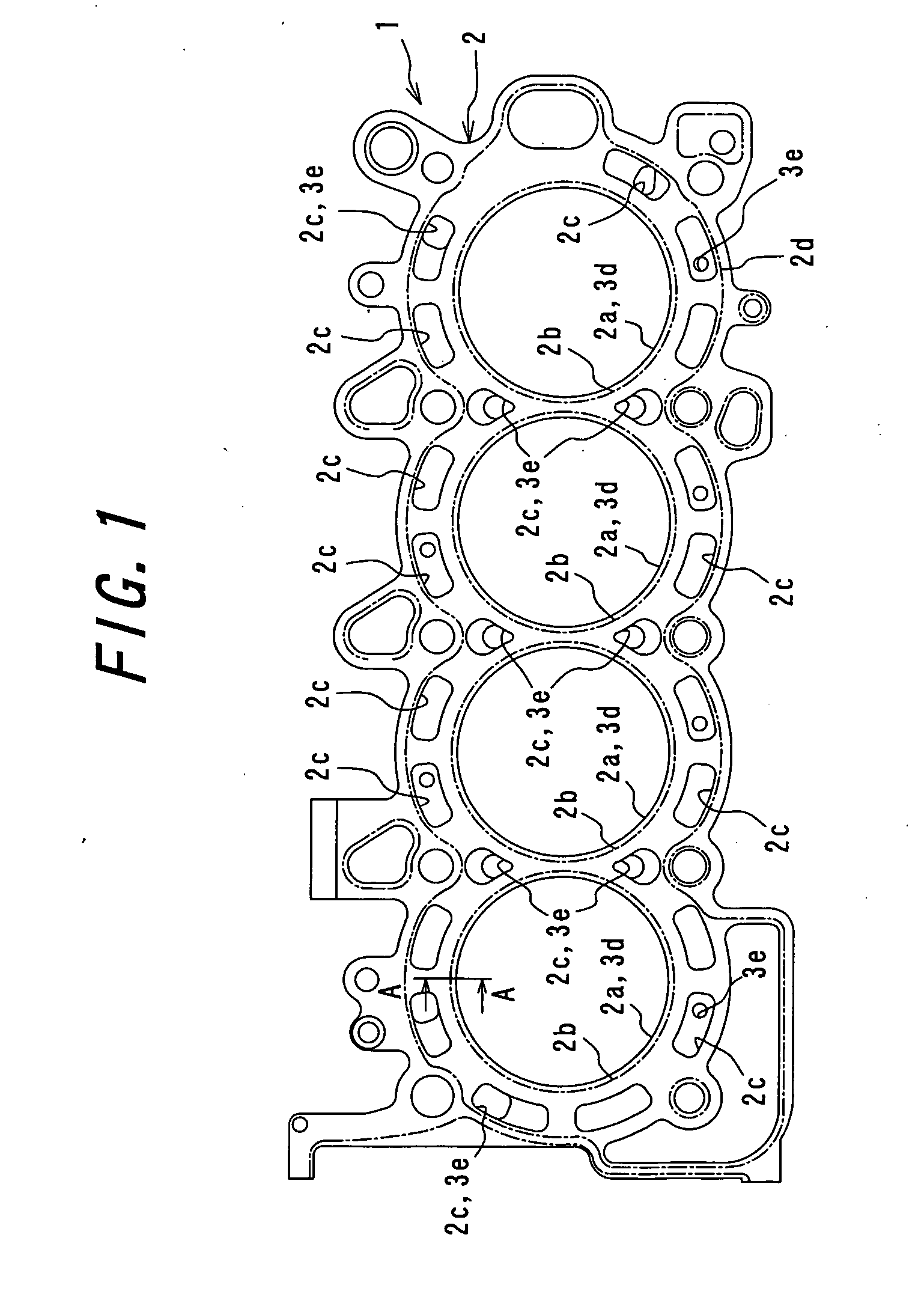
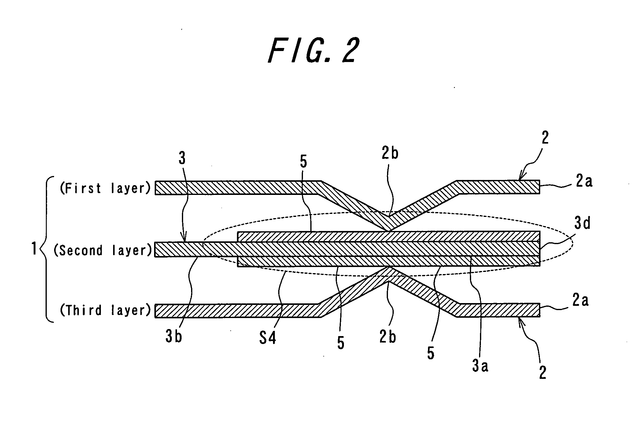
, which is taken along the A-A line in FIG. 1.

[0034] FIGS. 3(a) and 3(b) are explanatory views showing a method of providing a hard metal-plated layer on an auxiliary plate of the metal gasket of the above-described Example 1.

[0035]FIG. 4 is a cross-sectional view of a metal gasket for a cylinder head according to Example 5 of this invention in a similar position to FIG. 1.

[0036]FIG. 5 is a cross-sectional view of a metal gasket for a cylinder head according to Example 38 of this invention in a similar position to FIG. 1.

[0037]FIG. 6 is a cross-sectional view of a metal gasket for a cylinder head according to Example 39 of this invention in a similar position to FIG. 1.

[0038]FIG. 7 is a cross-sectional view of a metal gasket for a cylinder head according to Example 40 of this invention in a similar position to FIG. 1.

[0039]FIG. 8 is a cross-sectional view of a metal gasket for a cylinder head according to Example 41 of this invention in a similar position to FIG. 1.

[0040]FIG. ...


PUM


Abstract

A metal gasket for a cylinder head has two base plates each constructed from a metal plate and layered over each other, an auxiliary plate constructed from a metal plate and interposed between the base plates, and hard metal-plated layers. The base plates each have cylinder holes, annular beads, coolant holes, and an outer peripheral bead. The cylinder holes correspond with the bore of each cylinder. The annular beads have an angled cross-sectional shape. The coolant holes correspond with a coolant jacket of the cylinder block and with a coolant hole of the cylinder head. The outer peripheral bead has a cross-sectional shape sloping on one side and surrounds the beads and the coolant holes. Each of the layers is extended from a position more radially inward than an annular bead of a base plate to a position radially outward.

Description

TECHNICAL FIELD [0001] This invention relates to a metal gasket for a cylinder head to be interposed between a cylinder block and a cylinder head of an internal combustion engine. BACKGROUND ART [0002] As a metal gasket of this type, for example, there is known a metal gasket including two base plates respectively made of metal plates, and an auxiliary plate having a thinner plate thickness than those base plates and interposed between those base plates, in which each of the base plates includes cylinder holes formed so as to correspond to respective cylinder bores of a cylinder block of an internal combustion engine, annular beads of an angled cross-sectional shape formed around the respective cylinder holes, and coolant holes formed on outer peripheral portions of the respective annular beads so as to correspond to coolant jackets on the cylinder block and to coolant holes on a cylinder head of the internal combustion engine, while the auxiliary plate includes cylinder holes and c...

Claims


Application Information

Patent Timeline
Patent Type & Authority Applications(United States)
IPC IPC(8): F02F11/00F16J15/08F16J15/12
CPCF02F11/002F16J15/0818F16J2015/0862F16J2015/085F16J2015/0856F16J15/0825
Inventor HAMADA, YOSHIAKIYAJIMA, TAKASHIMURAKAMI, YASUNORIKATSURAI, TAKASHITABATA, MASAMUNE
Owner NIPPON LEAKLESS IND CO LTD
Why Eureka
Try Eureka