
Signal compressing circuit

a signal compression and circuit technology, applied in the direction of volume compression/expansion having semiconductor devices, transducer details, electrical transducers, etc., can solve the problems of distortion that cannot be achieved with very high volume level inputs, distortion may unavoidably occur beyond the range of supply voltage,

Inactive Publication Date: 2001-01-02
HANGER SOLUTIONS LLC
View PDF1 Cites 6 Cited by
  • Summary
  • Abstract
  • Description
  • Claims
  • Application Information

AI Technical Summary

Problems solved by technology

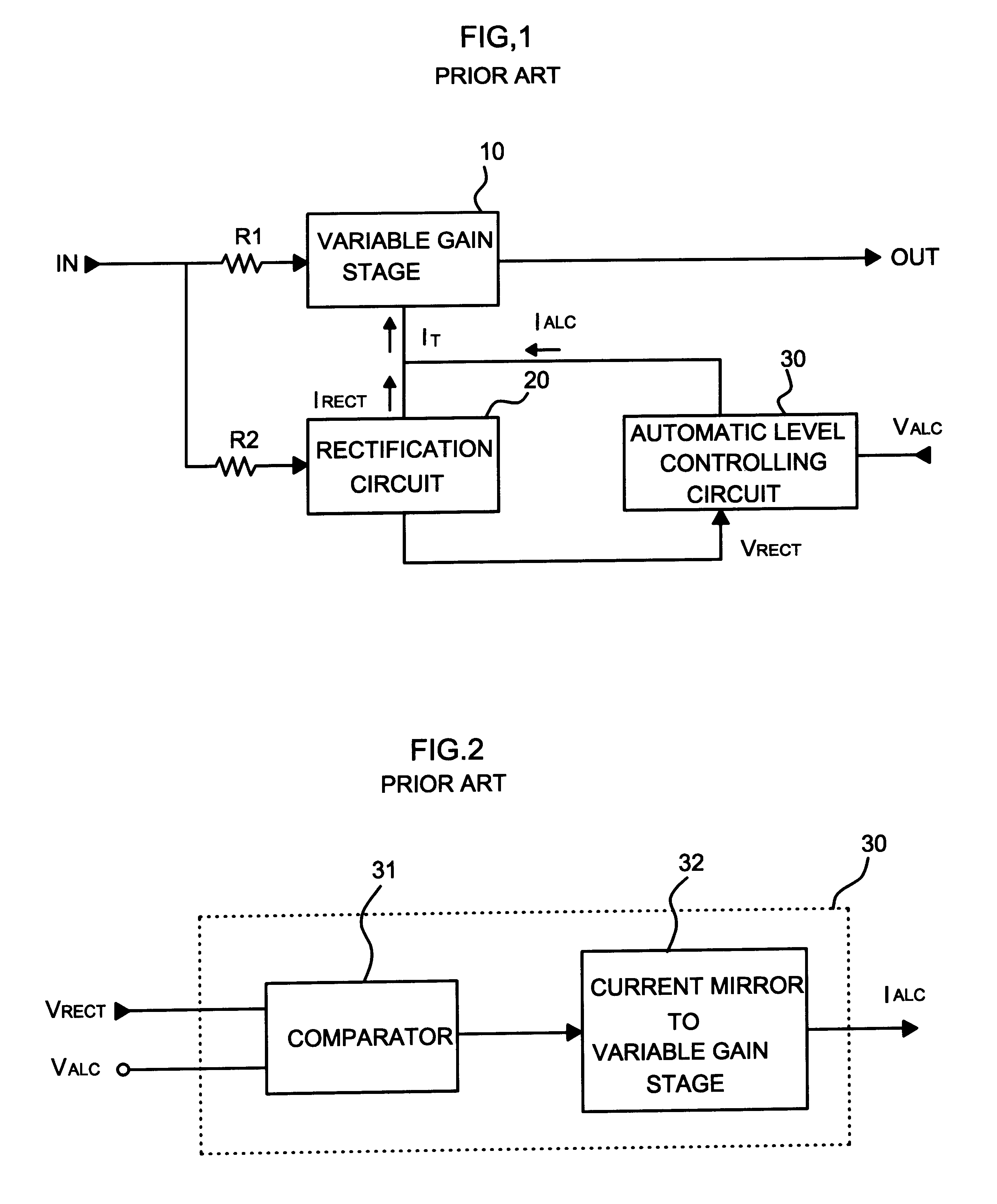
Thus the range of an input signal is so limited in producing output signals without distortion that effective attenuation of distortion cannot be attained with very high volume level inputs.
Also, since the range of supply voltage limits the maximum value of an output, distortion may unavoidably occurs beyond the range of the supply voltage when the level of an output, whose gain has been attenuated, exceeds the supply voltage.
To overcome this problem, the reference voltage of the automatic level controlling circuit might be greatly reduced, but this will limit the range of inputs having an optimized total harmonic distortion property, and deteriorate the signal compressing circuit's performance.

Method used


Image

  • Signal compressing circuit
  • Signal compressing circuit
  • Signal compressing circuit

Examples


Embodiment Construction

Reference will now be made in detail to the preferred embodiments of the present invention, examples of which are illustrated in the accompanying drawings.

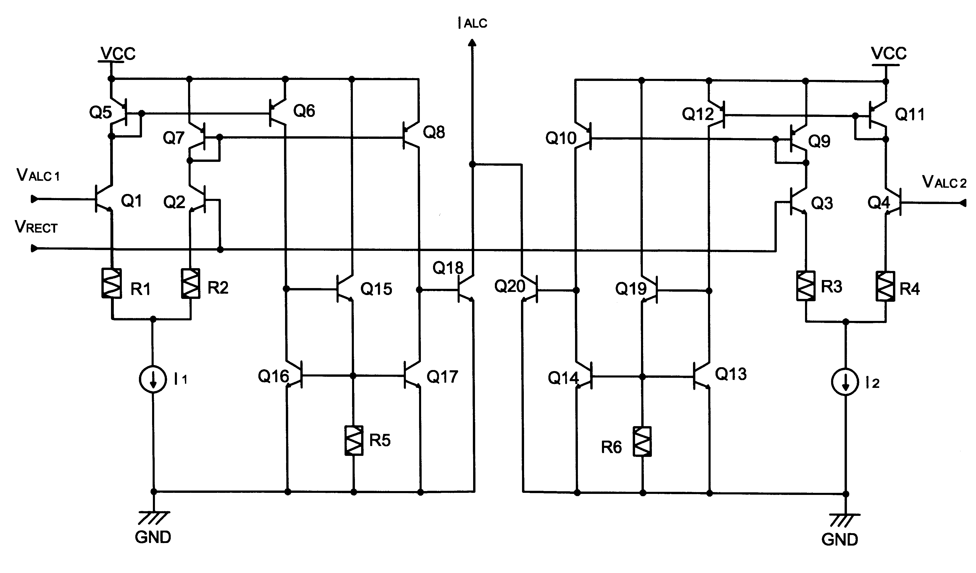
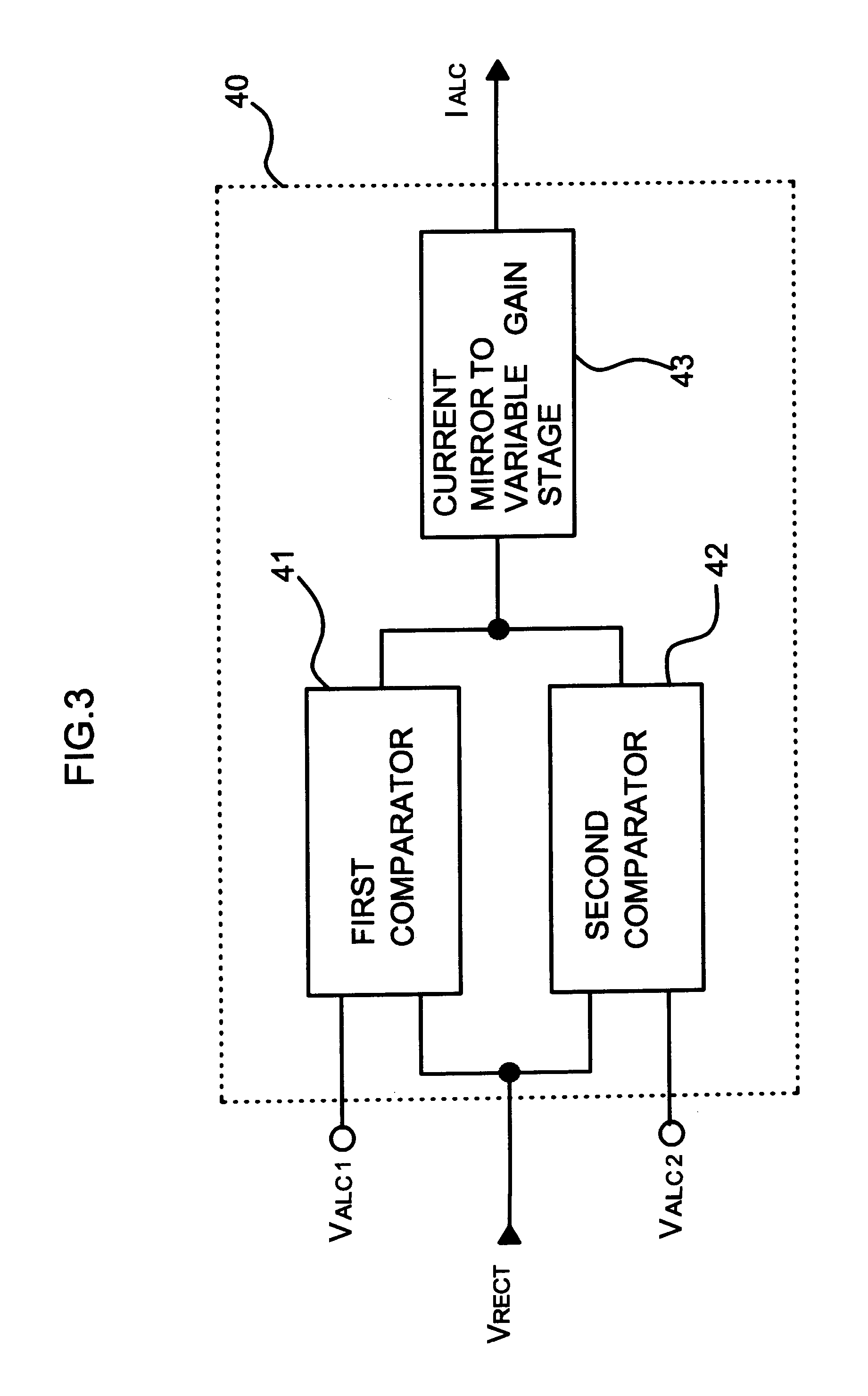
FIG. 3 is a block diagram of an automatic level controlling circuit in accordance with the present invention. FIG. 1 will also be referred to in explaining how the automatic level controlling circuit is connected to a Variable gain stage and a rectifying circuit.

As shown in FIG. 3, the automatic level controlling circuit 40 comprises two comparators 41 and 42, and one current mirror 43.

The reference voltage V.sub.ALC1 for the first comparator 41 is lower than the reference voltage V.sub.ALC2 of the second comparator 42. At a very high volume level from the input, the reference voltages V.sub.ALC1 and V.sub.ALC2 are used as the output control voltage, controlling the gain of Variable gain stage 10 so that the output is controlled to have an optimized, total harmonic distortion.

A change in the rectified voltage V.sub.RECT produces a...


PUM


Abstract

The present invention relates to a signal compressing circuit which amplifies an input signal on a logarithmic scale in an appropriate range, and has a variable gain stage, an input signal detector, and an automatic level controlling circuit, the automatic level controlling circuit including: a first comparator for comparing the input signal to a first reference voltage, and generating a signal proportional to the difference between them; a second comparator for comparing the input signal to a second reference voltage, and generating a signal proportional to the difference between them; and a current mirror for generating a controlling current in proportion to the output signal of the first and second comparators, thus controlling the gain of the variable gain stage in two steps so as to generate stable output signals.

Description

1. Field of the InventionThe present invention relates to a signal compressing circuit, specifically, a signal compressing circuit which is designed to expand the intensity range of input signals having a stable attenuation property.2. Discussion of Related ArtA signal compressing circuit is a device for amplifying input signals, transferred from communication equipment that directly transmits voice signals, to produce an appropriate range of signal amplitudes.The signal compressing circuit is generally not a linear amplifier but a non-linear amplifier that amplifies input signals according to a logarithmic scale. Since a voice transmission is limited by the signal amplitude and noise characteristic of transmission signals, a non-linear amplifier is needed to amplify input signals using gains differing according to the volume level of the signal.Such a non-linear amplifier increases the gain at very low volume signals but reduces the gain at very high volumes so that weak signal com...

Claims


Application Information

Patent Timeline
Patent Type & Authority Patents(United States)
IPC IPC(8): H03G7/00H04B1/62H03G7/06H04B1/64H03M7/30
CPCH03G7/06H04B1/64H03M7/30
Inventor KIM, SEONG-RYEOL
Owner HANGER SOLUTIONS LLC
Learn More