Inductor system for a submersible pumping system

a technology of pumping system and choke system, which is applied in the direction of fluid removal, borehole/well accessories, basic electric elements, etc., can solve the problems of low efficiency, low efficiency, and low efficiency of existing choke structure, and achieve the effect of reducing the number of chokes

Inactive Publication Date: 2001-01-23
CAMCO INT
View PDF21 Cites 63 Cited by
  • Summary
  • Abstract
  • Description
  • Claims
  • Application Information

AI Technical Summary

Problems solved by technology

Such faults can cause damage to the downstream dc circuitry necessitating removal and servicing, and resulting in down time and maintenance costs.
However, existing choke structures do not typically provide sufficient protection for the circuitry.
Such spikes can seri

Method used


Image

  • Inductor system for a submersible pumping system
  • Inductor system for a submersible pumping system
  • Inductor system for a submersible pumping system

Examples


Embodiment Construction

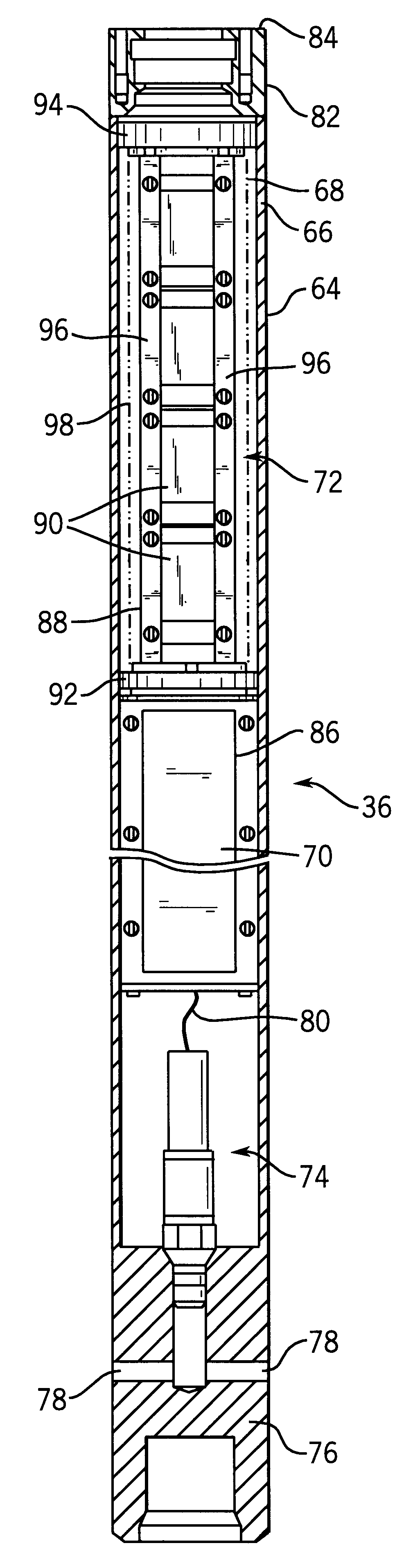
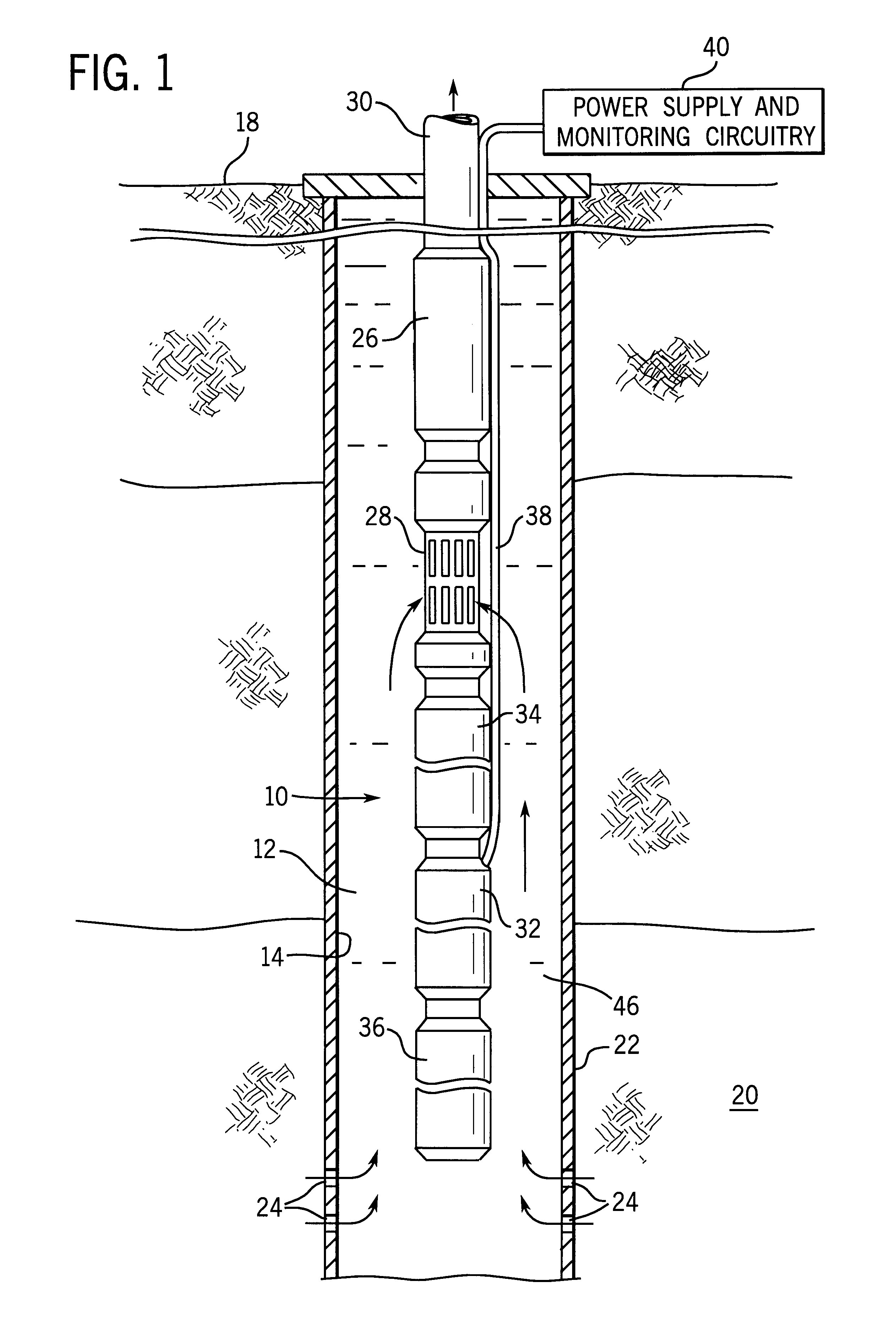
Turning now to the Figures, and referring first to FIG. 1, an equipment string 10 is illustrated in the form of a submersible pumping system deployed in a well 12. Well 12 is defined by a wellbore 14 which traverses a number of subterranean zones or horizons. Fluids 16 are permitted to flow into and collect within wellbore 14 and are transmitted, via equipment string 10, to a location above the earth's surface 18 for collection and processing. In the embodiment illustrated in FIG. 1, the pumping system is positioned adjacent to a production horizon 20 which is a geological formation containing fluids, such as oil, condensate, gas, water and so forth. Wellbore 14 is surrounded by a well casing 22 in which perforations 24 are formed to permit fluids 16 to flow into the wellbore from production horizon 20. It should be noted that, while a generally vertical well is illustrated in FIG. 1, the equipment string 10 may be deployed in inclined and horizontal wellbores as well, and in wells ...


PUM


Abstract

An inductor assembly is disclosed for protecting electronic circuitry in a downhole equipment string. The inductor assembly includes a plurality of modular inductors coupled to one another in series to provide the desired inductance. The modular inductors are supported by a support structure in a protective housing, such as in a common housing with the electronic circuitry. The inductor assembly is electrically isolated from the housing. The support structure may include insulative end members and rail members extending between the end members to which the inductors are secured. One or more insulative covers are provided around the inductors to further isolate the inductors from the housing. The inductor assembly dissipates energy in the event of certain failure modes of power supply circuitry or lines extending from the earth's surface. The inductor may be secured electrically between a neutral node in a Y-wound motor to prevent high voltage ac waveforms from damaging the electronic circuitry. Insulation of the inductors inhibits arcing with the housing, thereby inhibiting damage to the inductors or the electronic circuitry during such failure modes.

Description

1. Field of the InventionThe present invention relates generally to the field of submersible pumping systems of the type used in petroleum production and similar well applications. More particularly, the invention relates to a technique for protecting circuitry associated with such pumping systems, such as electronic circuitry for measuring or processing sensed or controlled parameters through the use of an inductor assembly.2. Description of the Related ArtA variety of equipment is known and is presently in use for handling fluids in wells, such as petroleum or gas production wells. For example, a known class of such equipment includes submersible pumping systems, which typically comprise a submersible electric motor and at least one pump coupled to the electric motor. The pumping system may also include such equipment as motor protectors, fluid separators, and measuring or control equipment, such as digital or analog circuitry.The equipment may be deployed in a wellbore in a varie...

Claims


Application Information

Patent Timeline
IPC IPC(8): E21B43/12H01F27/06
CPCE21B43/128H01F27/06
Inventor PEARSON, DONALD R.
Owner CAMCO INT
Why Eureka
Try Eureka