

High pressure discharge lamp
- Summary
- Abstract
- Description
- Claims
- Application Information
AI Technical Summary
Benefits of technology
Problems solved by technology
Method used
Image

Examples
embodiment 1
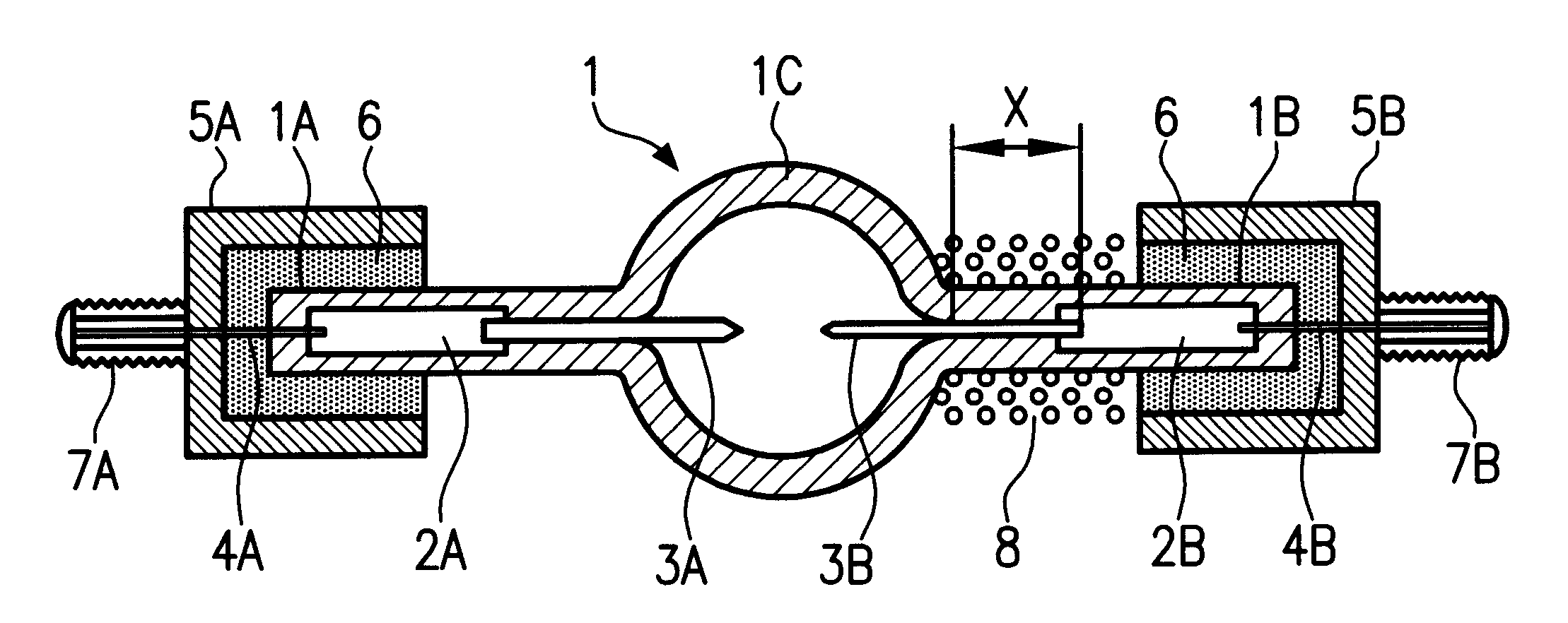
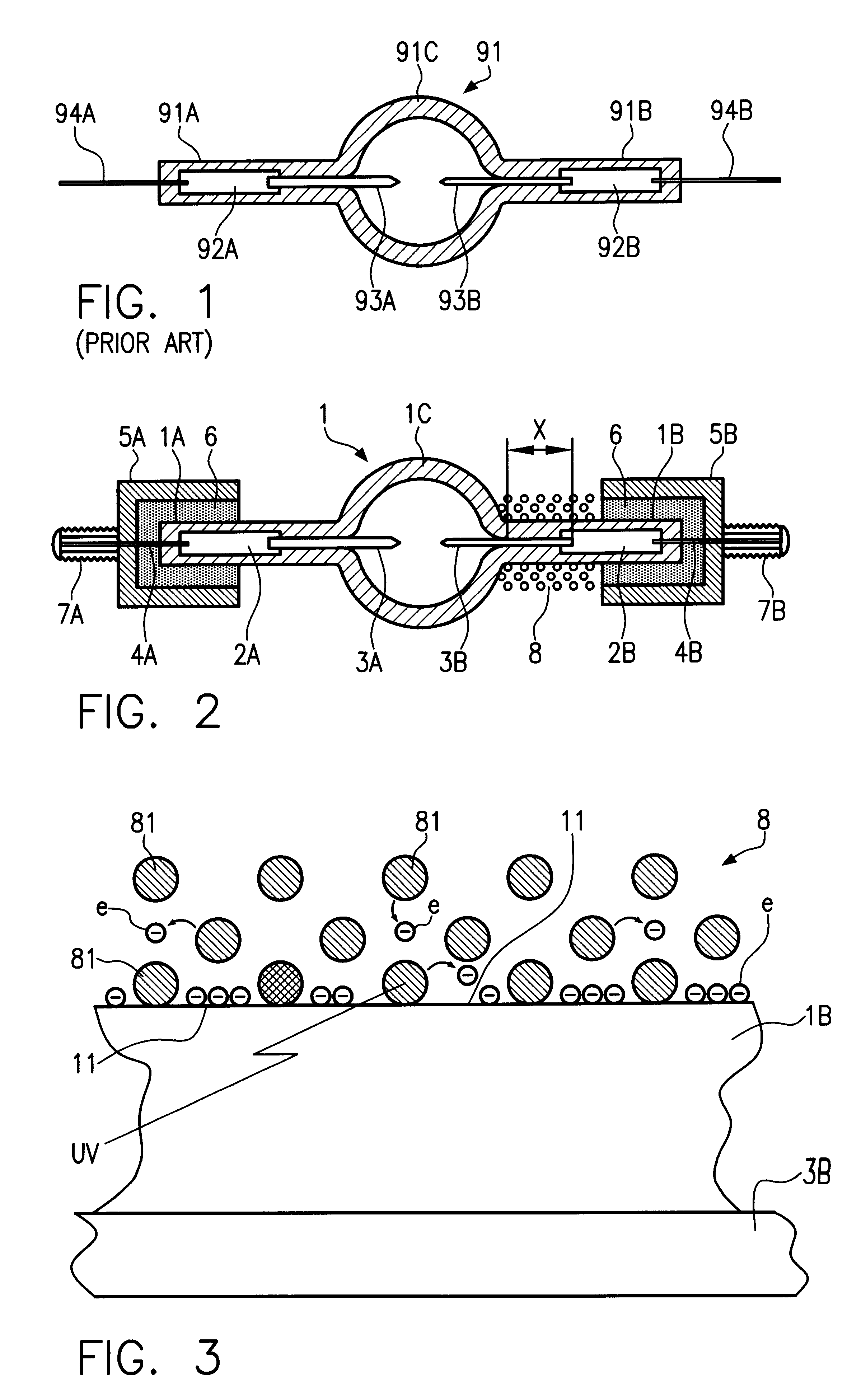
Twenty super high pressure mercury lamps of the direct current operating type (high pressure discharge lamps in accordance with the invention) with the arrangement shown in FIG. 2 and the specifications described below were produced.
Length of the discharge vessel 1: 11 mm
Outside diameter of the arc tube portion 1C: 11 mm
Inside volume of the arc tube portion 1C: 0.1 cm.sup.3
Outside diameter of the hermetically sealed portions 1A and 1B: 6 mm
Length of the hermetically sealed portions 1A and 1B: 30 mm
Length of the metal foils 2A and 2B: 25 mm
Diameter of the anode rod 3A: 0.8 mm
Length of the anode rod 3A: 11 mm
Diameter of the cathode rod 3B: 0.8 mm
Length of the cathode rod 3B: 10 mm
Distance between the electrodes (length of the arc): 1.5 mm
Diameter of the supply leads 4A and 4B: 0.8 mm
Length of the outer surface area X surrounding the cathode rod 3B: 5 mm
Type of metal wire comprising the conductive component 8: Fe--Cr alloy
Diameter of the metal wire comprising the conductive component 8...
embodiment 2
Besides the measure that the electrical components 8 and the cathode 3B were electrically connected to one another, the same measures as in embodiment 1 were implemented and 20 super high pressure mercury lamps of the direct current operating type (high pressure discharge lamp as claimed in the invention) were produced.
PUM
 Abstract
Description
Claims
Application Information