Method and circuit for checking the width of the air gap in a speed sensor

a speed sensor and air gap technology, applied in the direction of electrical/magnetically converting sensor output, instruments, devices using electric/magnetic means, etc., can solve the problems of unreliable direct modulation of information on the direction of rotation and high evaluation cos

Inactive Publication Date: 2001-01-30
CONTINENTAL AUTOMOTIVE GMBH
View PDF13 Cites 25 Cited by
  • Summary
  • Abstract
  • Description
  • Claims
  • Application Information

AI Technical Summary

Problems solved by technology

However, the expenditure for the evaluation is very high in the case of such a mode of procedure, since the output signal is not present in discrete form.
Moreover, the direct modulation of information on direction of rotation is an unreliable method, since interference has a strong influence.

Method used


Image

  • Method and circuit for checking the width of the air gap in a speed sensor
  • Method and circuit for checking the width of the air gap in a speed sensor
  • Method and circuit for checking the width of the air gap in a speed sensor

Examples


Embodiment Construction

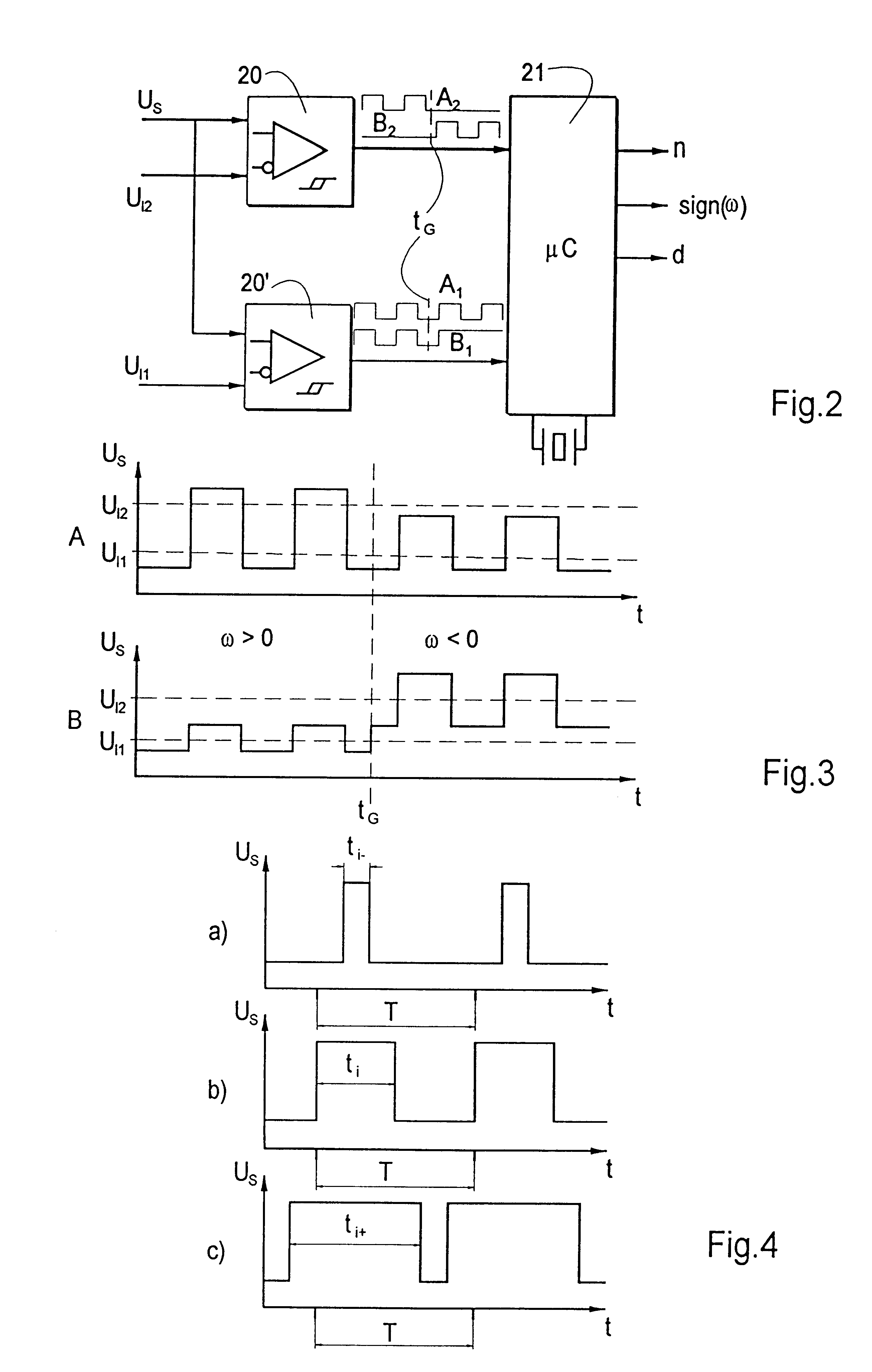
, the reference voltage U.sub.12 is overshot by the signal pulses only in the case of a negative direction of rotation. The reference voltage U.sub.11 is overshot in the case of a positive direction of rotation only during the signal pulses, and permanently in the case of a negative direction of rotation. As a consequence, the signal B2, exhibits a constant profile at a low level in the case of a positive direction of rotation. The signal B1 runs in a constant fashion at a high level in the case of a negative direction of rotation. In the other ranges, the signals are in the shape of a square wave. They have the same frequency there as the signal U.sub.S. In the Example A, the direction of rotation is therefore negative when the signal A2 is constant. In Example B, the direction of rotation is negative when the signal B1 is constant. Otherwise, the direction of rotation is positive.

In this way, two signals A.sub.1 and A.sub.2 and, respectively, B.sub.1 B.sub.2 are produced respectiv...


PUM


Abstract

In the case of a method for checking the width of the measuring air gap of a magnetic speed sensor, square-wave output signals are generated from the measurement signals of the sensor by means of at least one prescribable threshold value. The pulse duty factor of the output signals is held within a prescribed range in the case of an acceptable gap width. In the case of amplitudes of the measurement signal outside prescribed limits, the pulse duty factor deviates in a reliably measurable fashion from the prescribed range. A circuit has the means for carrying out this method.

Description

1. Field of the InventionThe invention relates to a method and a circuit for checking the width of the air gap between a coded rotor, which varies a magnetic flux, and at least one sensor element which is sensitive to magnetic fields and is provided for recording the rotary movement of the rotor, and to which a circuit is connected and in which measurement signals are generated by the magnetic variation during rotation of the rotor, the measurement signals being converted by the circuit into output signals which can be evaluated by a connected control device.2. Description of the Related ArtMagnetically based speed sensors are used, for example, in motor vehicles in connection with antilock systems. A circuit for such a sensor is known, for example, from WO 96 / 10751. The circuit changes the shape or the strength of the output signal as a function of the air gap width. The output signal is evaluated by the connected control device. However, the expenditure for the evaluation is very ...

Claims


Application Information

Patent Timeline
Patent Type & Authority Patents(United States)
IPC IPC(8): G01P1/00G01B7/14G01D5/244G01D5/12G01D3/08G01D5/14G01D5/16
CPCG01B7/14G01D3/08G01D5/24476G01D5/2448G01P1/00
Inventor WALLRAFEN, WERNER
Owner CONTINENTAL AUTOMOTIVE GMBH
Why Eureka
Try Eureka