Displacement sensor based on photonic crystal waveguides

Inactive Publication Date: 2006-05-18
RAMOT AT TEL AVIV UNIV LTD
View PDF3 Cites 22 Cited by
  • Summary
  • Abstract
  • Description
  • Claims
  • Application Information

AI Technical Summary

Benefits of technology

[0009] The present invention is of a displacement sensor comprising at least one pair of co-planar photonic crystal waveguide (PCWG) sections aligned along or parallel to a common axis and separated by a gap, one PCWG section of a pair operative to perform a displacement relative to the other section of the pair. The sensor is referred to hereinafter simply as “PCWG sensor”. In one embodiment, light coupled from one PCWG section into the other leaks into the gap, which itself has the properties of a “cross” PCWG, perpendicular to the first two. The amount of leaked energy and its

Problems solved by technology

Intensity modulation methods are commonly used, but provide inferior sensitivity relative to interferometry ones.
Existing MOEMS sensors are limited in the sensitivity that they can provide,

Method used


Image

  • Displacement sensor based on photonic crystal waveguides
  • Displacement sensor based on photonic crystal waveguides
  • Displacement sensor based on photonic crystal waveguides

Examples


example

Numerical Simulations

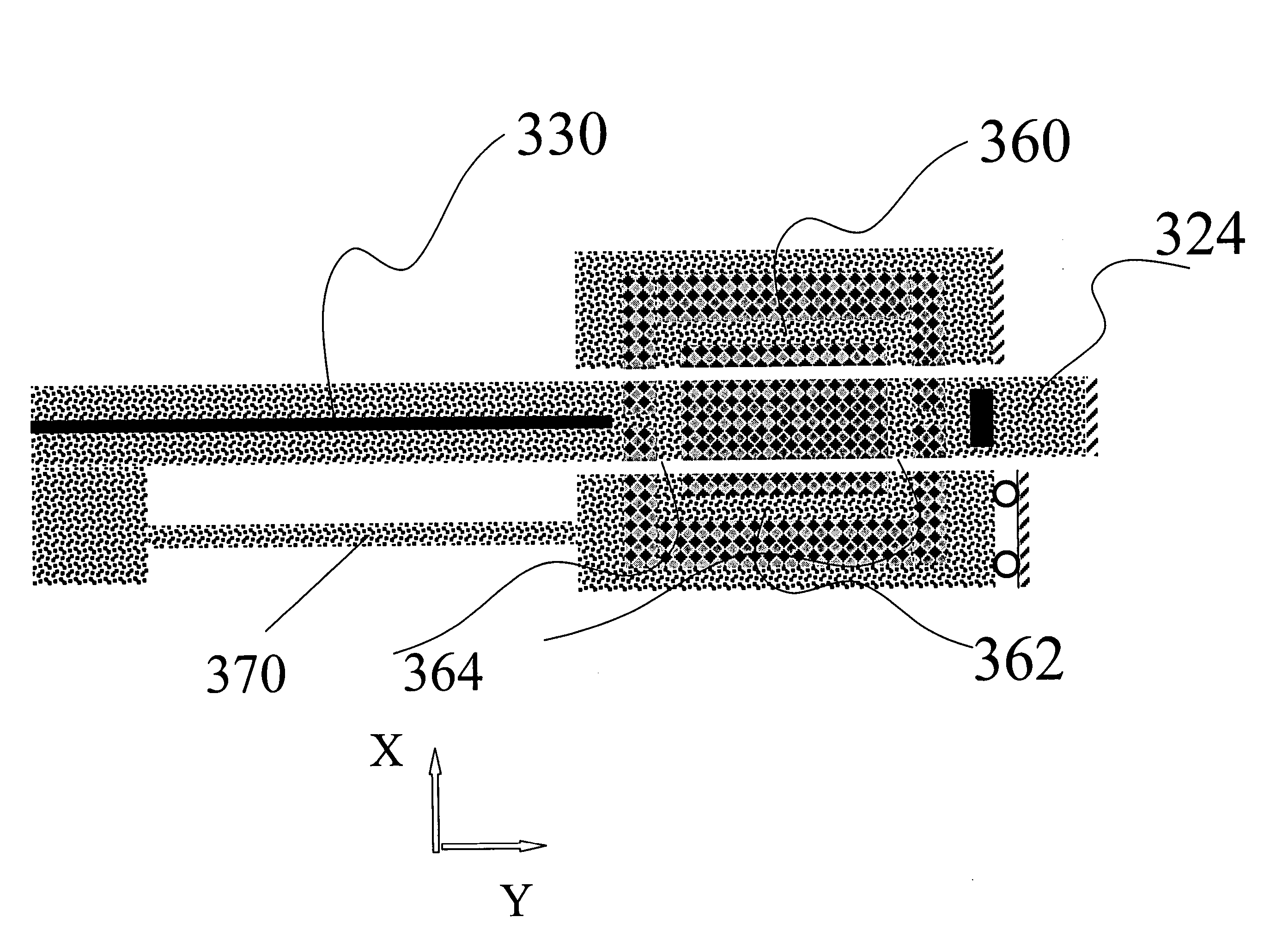
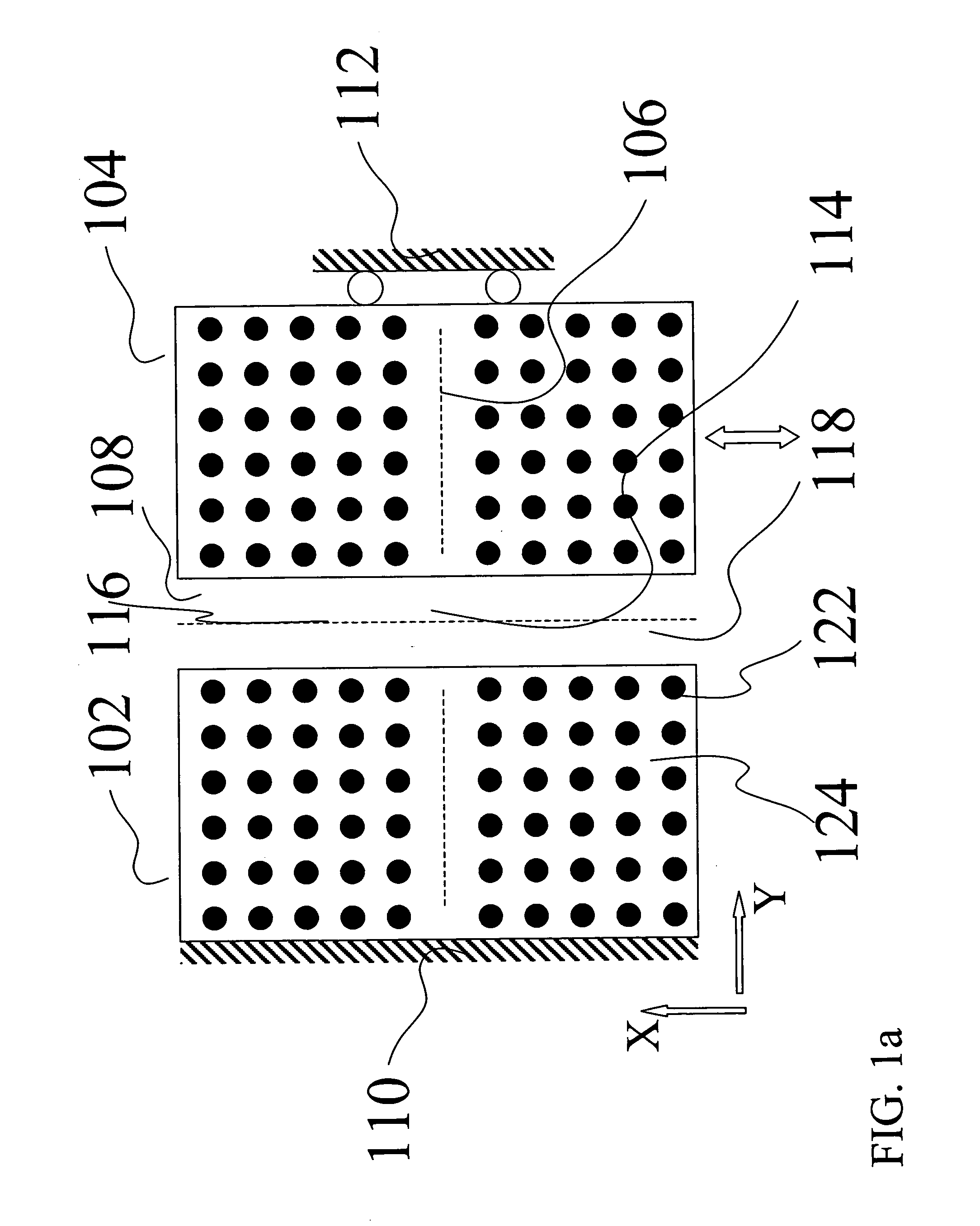
[0036] A numerical simulation of the field distribution inside a two-dimensional PC structure as in FIG. 1a and FIG. 3 is used to demonstrate the performance of our PCWG displacement sensor. We use a numerical code based on the Multifilament Current Model [Y. Leviatan and A. Boag, IEEE Trans. Antennas Prop., vol. 35, 1119 (1987)] to find the energy distribution and intensity exiting each PCWG for different displacements. Dielectric posts 122 are assumed to be cylinders with diameter 1.2 μm and a relative dielectric constant εr =8.41, separated by air and positioned on a square periodic lattice with a unit cell of 4 μm by 4 μm. All waveguides are W1-type. The light used has a 9.02 μm wavelength which can be generated using a CO2 laser, and which is within the bandgap of this PC structure. The numerical code computes the full solution of the propagation / scattering problem, based on the algorithm provided in Y. Leviatan and A. Boag, above. We use it to compute the...


PUM


Abstract

A displacement sensor comprising at least one pair of co-planar photonic crystal waveguide (PCWG) sections aligned along or parallel to a common axis and separated by a gap, one PCWG section of a pair operative to perform a displacement relative to the other section of the pair. In some embodiments, the sensor is linear, comprising two PCWG sections sperated by a gap that forms a cross PCWG, the displacement sensing performed preferrably differentially between two edges of the cross PCWG. In other embodiments, the sensor includes Mach Zehnder Interferometer (MZI) configurations with gaps between fixed and moving PCWG sections. Displacement induced changes in the gap widths are reflected in changes in an output parameter of the MZI.

Description

CROSS REFERENCE TO RELATED APPLICATIONS [0001] The present invention claims priority from U.S. Provisional Patent Applications No. 60 / 628,113 filed Nov. 17, 2004, the content of which is incorporated herein by reference.FIELD OF THE INVENTION [0002] The present invention relates to optical displacement sensors and more specifically to optical displacement sensors based on photonic crystal (PC) waveguides. BACKGROUND OF THE INVENTION [0003] Displacement sensors are used extensively in a host of applications, from simple, straightforward extensiometers to measurement of acceleration and vibrations. [0004] Optical displacement sensors are known. They rely generally on the precise measurement of the micro-displacement of a sub-millimeter flexible component. The displacement is measured with optical techniques, which can be defined as either intensity- or interferometry-based [T. Wang, S. Zheng, and Z. Yang, Sensors and Actuators A vol. 69, 134 (1998)]. Intensity modulation methods are c...

Claims


Application Information

Patent Timeline
IPC IPC(8): G01B9/02
CPCB82Y20/00G01D5/266G01P15/0802G01P15/093G02B6/1225G02B6/3508G02B6/3594G02B6/3596G01P2015/0828
Inventor NATHAN, MENACHEMSTEINBERG, BEN ZIONLEVY, ORENBOAG, AMIR
Owner RAMOT AT TEL AVIV UNIV LTD
Why Eureka
Try Eureka