
Integrated spectral encoder/decoder for optical CDMA communication system

a communication system and optical spectral encoder technology, applied in multiplex communication, optical code multiplex, instruments, etc., can solve the problems of cdma, high cost, cumbersome, etc., and achieve the stability, integration, and compact packaging requirements of the telecommunications industry.

Inactive Publication Date: 2004-10-19
UNIV OF MARYLAND BALTIMORE COUNTY
View PDF11 Cites 46 Cited by
  • Summary
  • Abstract
  • Description
  • Claims
  • Application Information

AI Technical Summary

Benefits of technology

This patent is about an optical CDMA system that uses an integrated device for multiple access. The system uses a broadband light source and an array waveguide grating to spread the light into different colors. The light is then encoded using a coded mask to transmit digital information. The system is designed to be compact and stable. The technical effect of this invention is to provide a more efficient and compact solution for optical CDMA communication networks.

Problems solved by technology

Coherent approaches require pico- or femtosecond pulsed lasers and phase detection systems that are generally complex, expensive, and cumbersome.
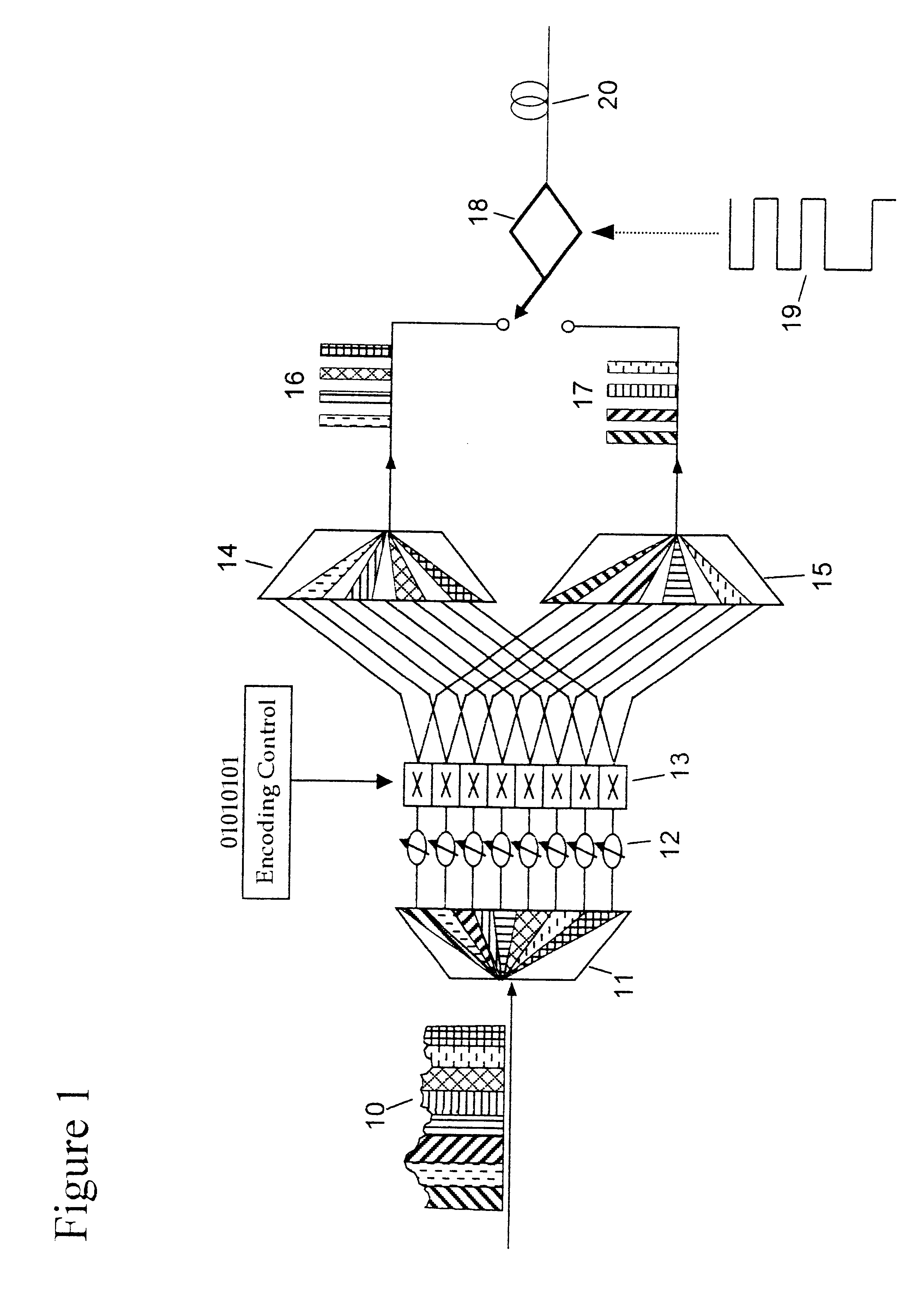
To date most implementations of CSK, including CDMA, have used free-space bulk optics, and are not compatible with the compact packaging requirements, stability, and integration needed by telecommunications industry.
The use of bulky optics introduces mismatch problems among encoder and decoder that affects the correlation detection process, such as the resolution and precision of the gratings, coding masks, etc.
However, using individual gratings, attenuators and switches will make devices too complex to be integrated.

Method used


Image

  • Integrated spectral encoder/decoder for optical CDMA communication system
  • Integrated spectral encoder/decoder for optical CDMA communication system
  • Integrated spectral encoder/decoder for optical CDMA communication system

Examples


Embodiment Construction

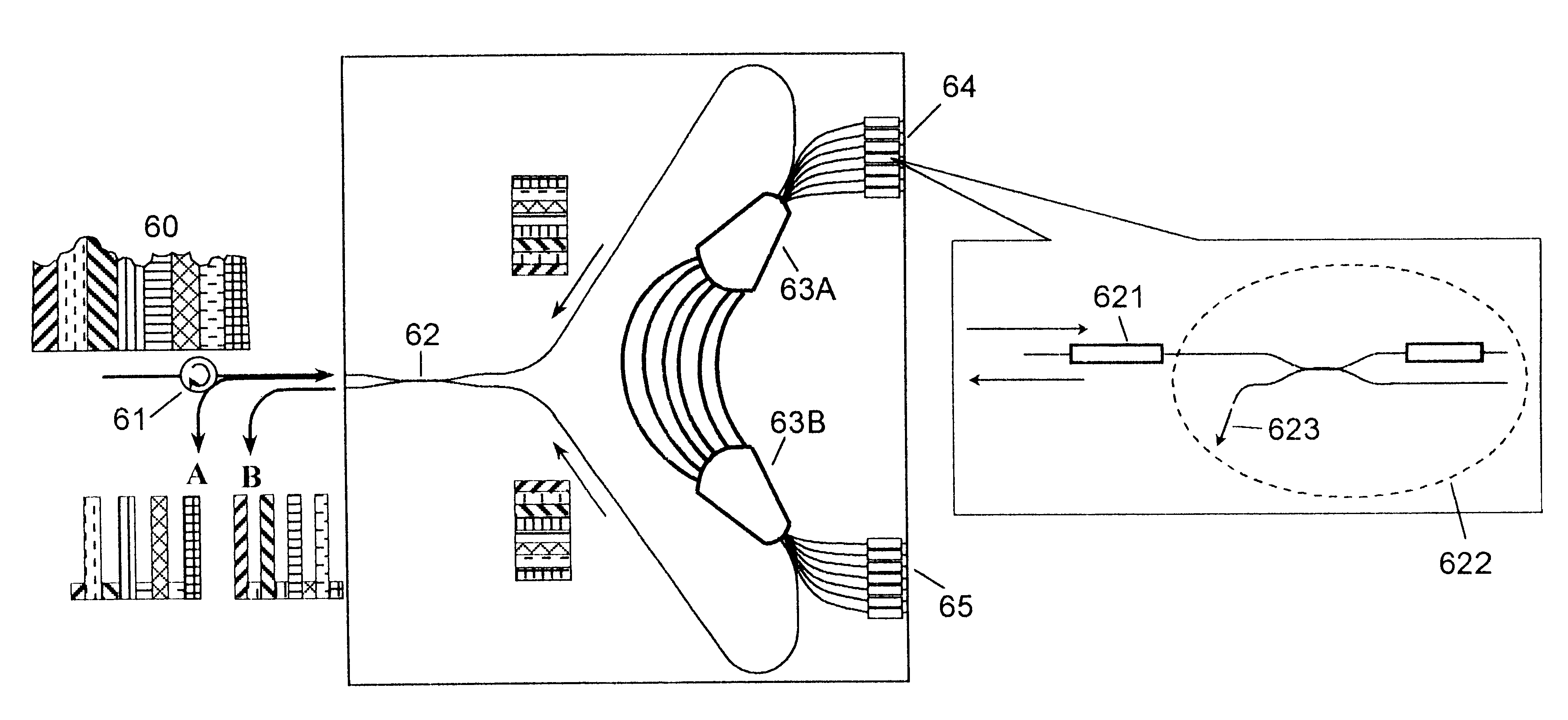
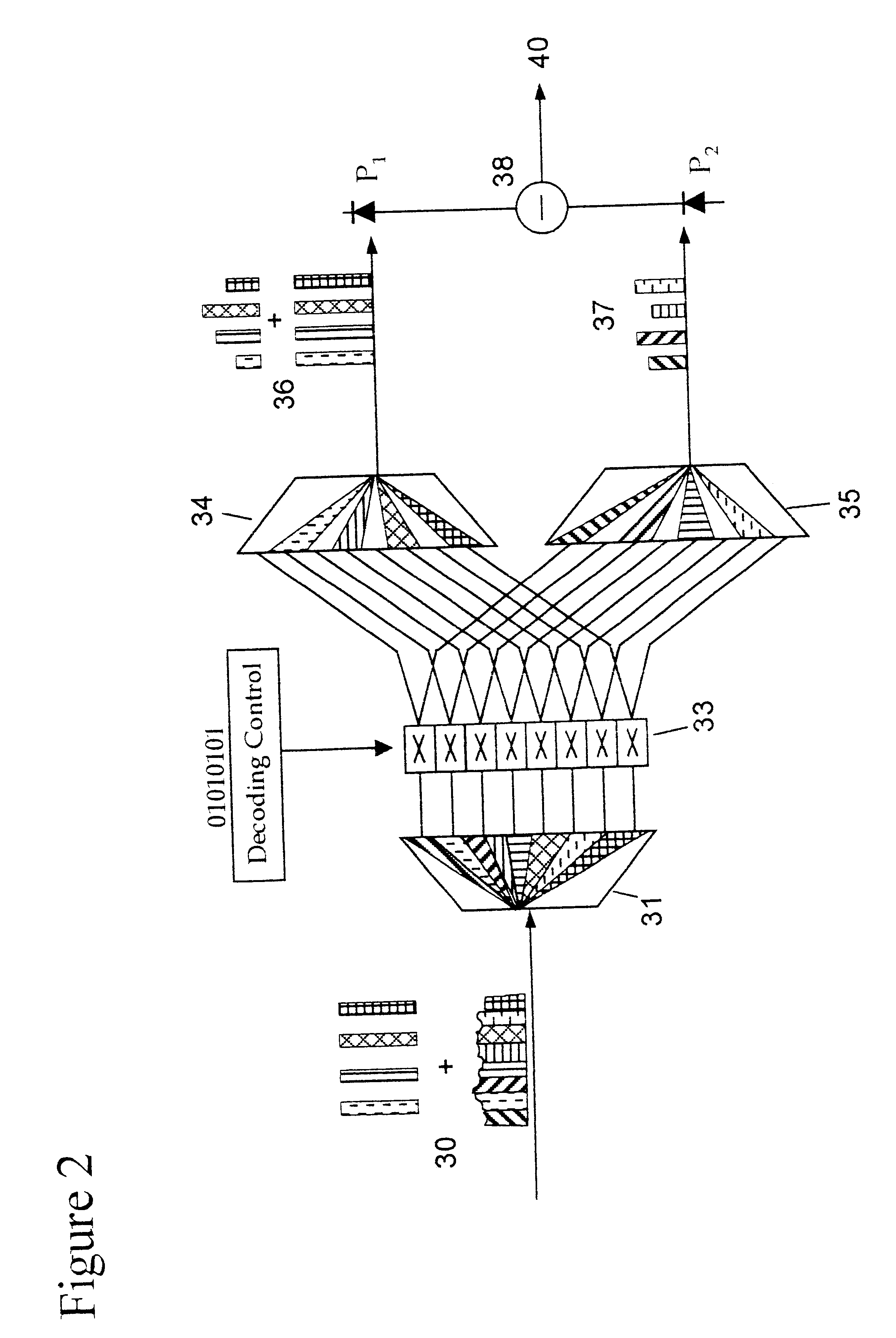
The complete system as shown in FIG. 4 comprises a circulator 61, a 3 dB coupler 62, a single doubled ended AWG 63A / 63B, an array of thermooptic phase-shifters 621 and tunable attenuators 622, and a coated, reflecting surface 64 / 65. The circulator allows the signal to transmit only in one direction. The 3-dB coupler 62 divides the signal into two paths. The double-ended AWG 63A / 63B functions as described in connection with FIG. 2 to decompose the input broadband light source into individual spectral components. Each spectral component then passes through a thermooptic phase shifter. The thermooptic phase-shifters 621 and attenuator 622 can adjust the phase-shift and the attenuation thermal-optically. The reflecting surface 64 / 65 creates virtual counterparts from the real counterparts of the incident image. The whole structure and its image form a large Mach-Zehnder interferometer (MZI) with an AWG, phase shifters, and tunable attenuators in each arm as shown in FIG. 5a. The attenuat...


PUM


Abstract

The encoder / decoder design for spectrum-encoded optical CDMA systems uses waveguide circuits monolithically integrated on one chip to fulfill essential encoding and decoding functions. The integrated device functions as a 1x2 wavelength selective Mach-Zehnder interferometer switch to encode the input broadband light source and to decode the transmitted spectrally encoded signals. The device comprises a frontal 3-dB coupler, a double-ended arrayed-waveguide grating (AWG), and arrays of thermooptic phase shifters and attenuators, together with their symmetric images reflected from the high-reflection coated facet, to realize all required functionality. The thermooptic phase shifters and attenuators are programmable through electronic interface to realize programmable encoding and decoding capabilities. The attenuators are used to equalize the powers and to increase the ON / OFF extinction ratio of all spectral chips.

Description

(1) Field of the InventionThis invention relates to optical telecommunication technology, particularly to an optical spectral encoder / decoder for a Code Division Multiple Access (CDMA) communication system.(2) Brief Description of the Related ArtFiber-optics communication links are gaining great popularity because the transmission medium has a comparatively unlimited bandwidth and excellent attenuation properties.In a broadcast and select communication system, it is desirable that a number of end-user stations be able to interconnect their respective communication links through a common bus. This ability is known as multiple access. Two common multiple access systems are the time division multiple access (TDMA) and the Code Division Multiple Access (CDMA). In a TDMA system, each user is assigned a time slot. In a CDMA system, each user is assigned a special code. Signals are separated using a correlator that accepts only signal energy from the key variable binary (sequence) code use...

Claims


Application Information

Patent Timeline
Patent Type & Authority Patents(United States)
IPC IPC(8): G02B6/34H04B1/707H04J14/00
CPCG02B6/12007G02B6/12019H04J14/005H04B1/707G02B6/29352H04B2201/70715
Inventor LEE, CHAUHAN DANIELZHONG, SHANCHEN, YUNG JUI
Owner UNIV OF MARYLAND BALTIMORE COUNTY
Learn More