Distributed optical fiber vibration sensor

A technology of vibration sensor and distributed optical fiber, which is applied in the field of sensors, can solve the problems of not meeting the practical application of real-time detection, increasing the cost of signal detection circuit, and not being able to reproduce the action function, so as to achieve long-distance detection, compensation of polarization fading phenomenon, The effect of cost reduction

Inactive Publication Date: 2011-08-31
SHANGHAI INST OF OPTICS & FINE MECHANICS CHINESE ACAD OF SCI
View PDF6 Cites 44 Cited by
  • Summary
  • Abstract
  • Description
  • Claims
  • Application Information

AI Technical Summary

Problems solved by technology

[0004] At this stage, most of the optical fiber sensing systems cannot reproduce the action function of the external mechanical vibration interference source, or some can reproduce, but the optical path is relatively complicated, forming multiple optical outputs
This increases the cost of the signal detection circuit
Although some structures can detect single-point interference and accurately locate it, they cannot make accurate judgments when multiple points interfere at the same time, and cannot meet the practical application of real-time detection.
In order to prevent polarization fading, polarization maintaining fiber or polarization controller is used, which increases the cost of the sensing system

Method used


Image

  • Distributed optical fiber vibration sensor
  • Distributed optical fiber vibration sensor
  • Distributed optical fiber vibration sensor

Examples


Embodiment Construction

[0026] The present invention will be described in further detail below in conjunction with the accompanying drawings and embodiments.

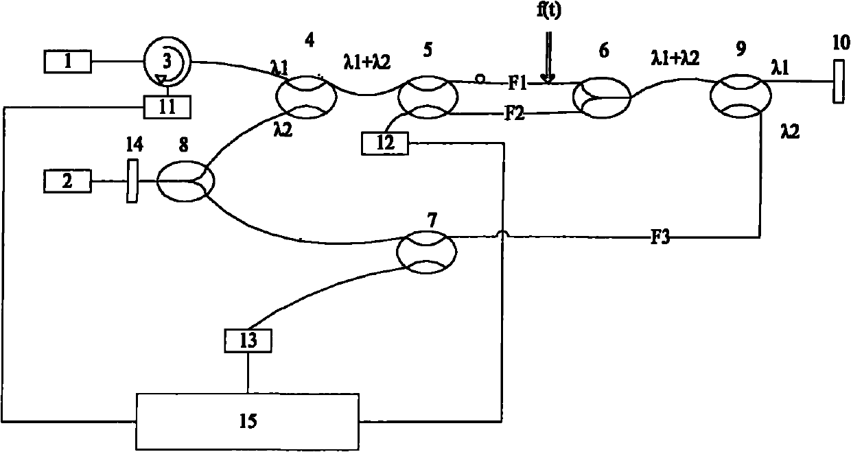
[0027] figure 1 It is a structural schematic diagram of the distributed optical fiber vibration sensor of the present invention. It can be seen from the figure that the distributed optical fiber vibration sensor of the present invention comprises a signal processing device 15, a first sensing optical fiber F1, a second sensing optical fiber F2, a third sensing optical fiber F3, a broadband light source 1, a narrowband light source 2, and an optical ring 3, the first optical wavelength division multiplexer 4, the second optical wavelength division multiplexer 9, the first coupler 5, the second coupler 6, the third coupler 7, the fourth coupler 8, the Faraday rotating mirror 10, The first photodetector 11, the second photodetector 12, the third photodetector 13 and the optical isolator 14; the connection relationship of the above-mentioned comp...


PUM


Abstract

The invention discloses a distributed optical fiber vibration sensor. The distributed optical fiber vibration sensor is characterized in that: on the basis of the optimized combination of the interference principles of a Sagnac interferometer and a Mach-Zehnder interferometer, the distributed optical fiber vibration sensor comprises a signal processing device, a first sensing optical fiber, a second sensing optical fiber, a third sensing optical fiber, a wideband light source, a narrowband light source, an optical circulator, a first optical wavelength division multiplexer, a second optical wavelength division multiplexer, a first coupler, a second coupler, a third coupler, a fourth coupler, a Faraday rotating mirror, a first photodetector, a second photodetector, a third photodetector and an optoisolator. The distributed optical fiber vibration sensor has a simple structure and can be used for monitoring outside disturbance and positioning multi-point interferences in real time; the demodulation work is relative simple and polarization maintaining optical fibers can be prevented from being used; and by adopting the Faraday rotating mirror, the phenomenon of polarization state fading due to double refraction can be also compensated.

Description

technical field [0001] The invention relates to a sensor, especially a distributed optical fiber vibration sensor, which can reproduce the change of external vibration and locate the vibration point. Background technique [0002] Pipeline transmission has the advantages of economy, safety, high efficiency, and stability, and is widely used in the transportation of oil, natural gas, water and other fluids all over the world. Pipeline leaks occur from time to time due to factors such as corrosion, geographical and climatic changes, construction around pipelines, and vandalism. This not only brings great economic losses, but also pollutes the environment. Therefore, the timely detection and location of pipeline leakage has important practical significance. [0003] Distributed optical fiber sensing technology is a new technology developed in recent years, which has the characteristics of corrosion resistance, high sensitivity, large dynamic range and long-distance continuous m...

Claims


Application Information

Patent Timeline
Patent Type & Authority Applications(China)
IPC IPC(8): F17D5/02
Inventor 成倩陈柏陈嘉琳李国扬张承涛陈宇陈福昌朱小龙胡佳成
Owner SHANGHAI INST OF OPTICS & FINE MECHANICS CHINESE ACAD OF SCI
Why Eureka
Try Eureka