High gain resonant modulator system and method

a resonant modulator and high gain technology, applied in the field of high gain resonant modulator system and method, can solve the problems of inability to optimize analog applications, inability to manufacture hybrids, and inability to meet the requirements of high-gain resonant modulators, so as to improve the slope efficiency, improve the operation, and increase the analog link gain

Inactive Publication Date: 2006-04-20
PHOTONICSYST
View PDF15 Cites 40 Cited by
  • Summary
  • Abstract
  • Description
  • Claims
  • Application Information

AI Technical Summary

Benefits of technology

[0013] The optical resonant modulator of the invention is particularly well suited for use as a broadband modulator for high gain analog applications and results in improved slope efficiency for increased analog link gain. It does not require any waveguide crossovers. In one aspect, the invention provides near theoretical performance, independent of intrinsic material losses. The resonator lends itself to hybrid integration so that optimal advantages of different materials can be combined for improved operation. By physically separating the functions of low loss re

Problems solved by technology

Current designs for the resonant modulators, however, suffer from a number of limitations.
First, the use of a balanced MZI, with 3 dB directional couplers, has been considered to date for digital applications, and may not be optimi

Method used


Image

  • High gain resonant modulator system and method
  • High gain resonant modulator system and method
  • High gain resonant modulator system and method

Examples


Embodiment Construction

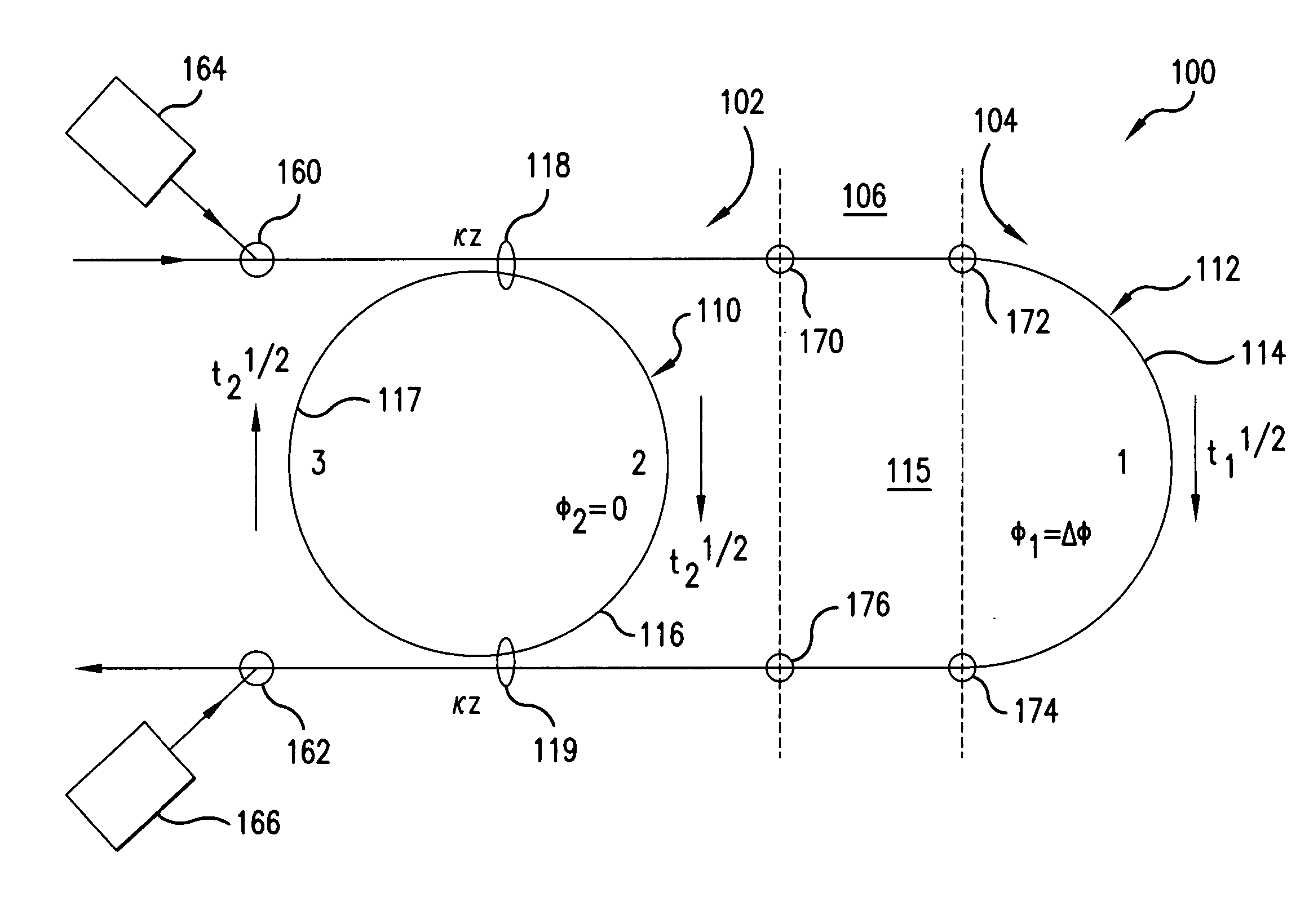
[0031] In general, for an arbitrary MZI, the total MZI phase shift Δφt, which is the phase difference between the arms of the interferometer, can be defined as:

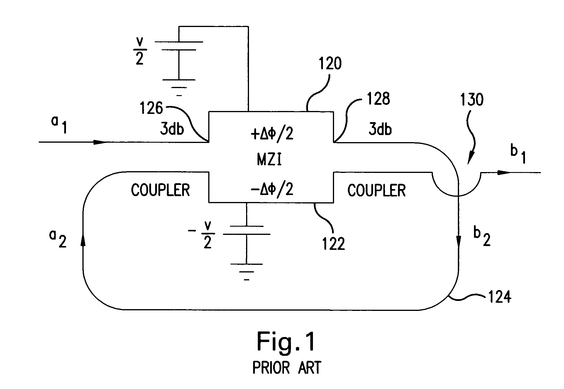
Δφt=φ1−(−φ2)=sΔφt+(1−s)Δφt  (1) [0032] where φ1 and −φ2 are the phase changes in arms 1 and 2, respectively, and s is a parameter describing the asymmetry of the MZI. In general, 0≦s≦1. For the arrangement shown in FIG. 1, eq.1 is satisfied by s=½.

[0033] For this arrangement, 3 dB couplers 126 and 128 divide the optical power of a single input in half. Stated in another way, κz is constrained to 45 deg, where κ is the coupling coefficient in the directional coupler and z is its length. It can be shown that these are the only conditions under which critical coupling, where the power output is 0, can be obtained for all values of Δφ, independent of κz.

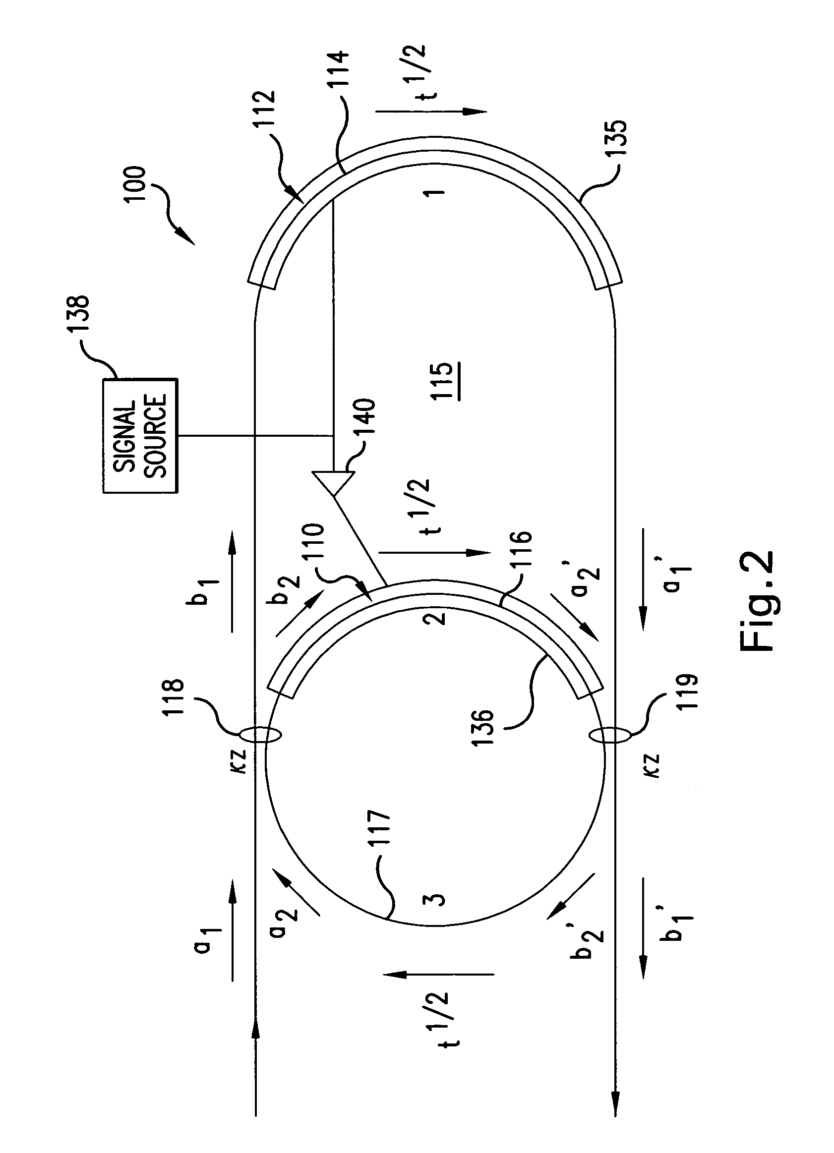
[0034]FIG. 2 illustrates an optical resonant modulator, which has been constructed according to the principals of the present invention.

[0035] The optical resonant modulator 1...


PUM


Abstract

An optical resonant modulator includes an optical ring resonator and an optical loop that is coupled to the optical ring resonator by two couplers. The optical ring resonator can have a hybrid design in which the ring resonator is formed on an electro-optically passive material and the optical loop is formed on an electro-optically active material. An amplification section can be inserted between the electro-optically passive and the electro-optically active sections. In analog applications, an optical resonator includes a Mach Zehnder interferometer section having an input and an output, with a feedback path coupling the output to the input. Applications of the optical modulator of the invention, and a method for modulating an optical signal also are disclosed.

Description

GOVERNMENT SUPPORT [0001] The invention was made with government support under Grant / Contract No. F30602-00-C-0128 awarded by Defense Advanced Research Projects Agency (DoD). The government has certain rights in the invention.BACKGROUND OF THE INVENTION [0002] Mach Zehnder interferometers (MZIs) often are used to modulate the amplitude or intensity of an optical signal. MZIs are most often deployed as modulators in digital links. However, they also have application in analog links, such as in multi- or sub-octave remote antenna links. [0003] Generally, deployed MZI modulators are monolithic devices formed from an electro-optically active material such as lithium niobate. The MZIs have two couplers and two arms. Electrodes are provided for controlling the electric field in the region of the two arms. An input signal is divided between the two arms by a first coupler, with the divided signal passing through the two arms, and then recombined by the second coupler. Often, the arms have ...

Claims


Application Information

Patent Timeline
IPC IPC(8): G02F1/035
CPCG02F1/035G02F2001/212G02F2203/15G02F1/225G02F1/212
Inventor BURNS, WILLIAM K.PRINCE, JOELLEACKERMAN, EDWARD
Owner PHOTONICSYST
Why Eureka
Try Eureka